
Advanced Fault Diagnosis Techniques for Industrial Compressors
By Nick Li · August 10, 2026 · Technical Articles
Fault diagnosis is the systematic process of identifying, locating, and characterizing abnormalities in compressor operation. Effective diagnosis prevents catastrophic failures, reduces unplanned downtime, and optimizes maintenance resource allocation. This article presents advanced diagnostic techniques developed from field experience and industry best practices.
1. Vibration-Based Fault Diagnosis
Vibration analysis remains the most powerful diagnostic tool for reciprocating and centrifugal compressors. Different fault types produce characteristic vibration signatures that can be identified through spectral analysis, waveform examination, and phase relationships.
| Fault Type | Dominant Frequency | Key Indicator |
|---|---|---|
| Unbalance | 1x running speed | Radial vibration dominant |
| Misalignment | 2x running speed | Axial vibration prominent |
| Looseness | Multiple harmonics | Sub-harmonics present |
| Bearing wear | High frequency (1-20 kHz) | Impact pulses on waveform |
| Valve leak | Impact at valve frequency | Non-periodic impacts |
2. Temperature Monitoring and Thermal Imaging
Abnormal temperature patterns reveal bearing distress, lubrication failure, valve leakage, and process flow problems. Infrared thermography enables non-contact inspection of critical components during operation.
- Monitor bearing temperatures continuously; trend above 90 C requires investigation
- Use thermal imaging to detect hot spots on cylinders, valves, and piping
- Compare discharge temperature across cylinders for balance verification
- Track lube oil temperature differential (inlet vs. outlet) for cooler efficiency
- Identify blocked or restricted cooling passages via localized overheating
3. Pressure-Volume (P-V) Diagram Analysis
The P-V diagram is the fingerprint of reciprocating compressor cylinder performance. By measuring dynamic pressure within the cylinder throughout the compression cycle, technicians can identify valve leakage, piston ring wear, and cylinder clearance issues with high precision.
3.1 Common P-V Deviations
| Deviation | Possible Cause | Action |
|---|---|---|
| Loss of area | Suction valve leakage | Inspect/replace suction valve |
| Higher expansion line | Discharge valve leakage | Inspect/replace discharge valve |
| Reduced compression ratio | Piston ring wear | Measure ring clearance |
| Erratic curve | Liquid carryover | Check KOD/scrubber level |
4. Oil Analysis and Wear Particle Detection
Lubricating oil carries critical information about the internal health of the compressor. Regular oil sampling and analysis can detect bearing wear, gear deterioration, and contamination before secondary damage occurs.
- Monitor metallic particle count trend (Fe, Cu, Sn, Pb, Cr) every 500 operating hours
- Check oil viscosity, total acid number (TAN), and water content quarterly
- Use ferrography for detailed wear particle morphology analysis
- Set alarm thresholds based on ISO 4406 cleanliness codes
- Correlate oil analysis results with vibration trends for cross-validation
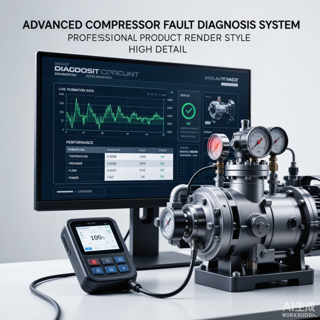
Figure 1: Advanced fault diagnosis system with vibration and performance monitoring
5. Acoustic Emission Monitoring
Acoustic emission (AE) technology detects high-frequency stress waves generated by crack propagation, valve impact, and friction events. AE sensors mounted on cylinder externals can detect valve leakage at an early stage, complementing traditional vibration analysis.
- Install AE sensors on each cylinder head and valve cover
- Establish baseline AE energy levels during normal operation
- Set relative alarm thresholds at 2x baseline for early warning
- Correlate AE burst patterns with crank angle for fault localization
- Integrate AE data with P-V diagram analysis for comprehensive diagnosis
6. Integrated Diagnostic Approach
No single diagnostic technique provides complete coverage. An integrated approach combining vibration, temperature, P-V analysis, oil analysis, and acoustic emission provides the most reliable fault identification and reduces false alarms.
| Fault Scenario | Primary Indicator | Confirmatory Method |
|---|---|---|
| Valve leakage | P-V diagram deviation | AE + temperature rise |
| Bearing failure | Vibration spectrum | Oil analysis + temperature |
| Piston ring wear | P-V area loss | Blowby measurement |
| Rod loading exceedance | Rod load monitor | Vibration phase analysis |
7. Diagnostic Decision Support
Modern diagnostic systems incorporate machine learning algorithms that learn from historical fault data to predict impending failures. These systems can prioritize maintenance actions, estimate remaining useful life, and automatically generate work orders based on diagnostic confidence levels.
- Implement a centralized condition monitoring database with trend analysis
- Define diagnostic confidence levels (possible, probable, confirmed) for each fault
- Create fault decision trees for systematic troubleshooting
- Train maintenance personnel on multi-parameter diagnostic interpretation
- Review and update diagnostic rules based on actual failure case studies
Source: Compressor Technology Editorial Reference