
Centrifugal Chiller Maintenance and Performance Optimization
By Nick Li · August 10, 2026 · Technical Articles
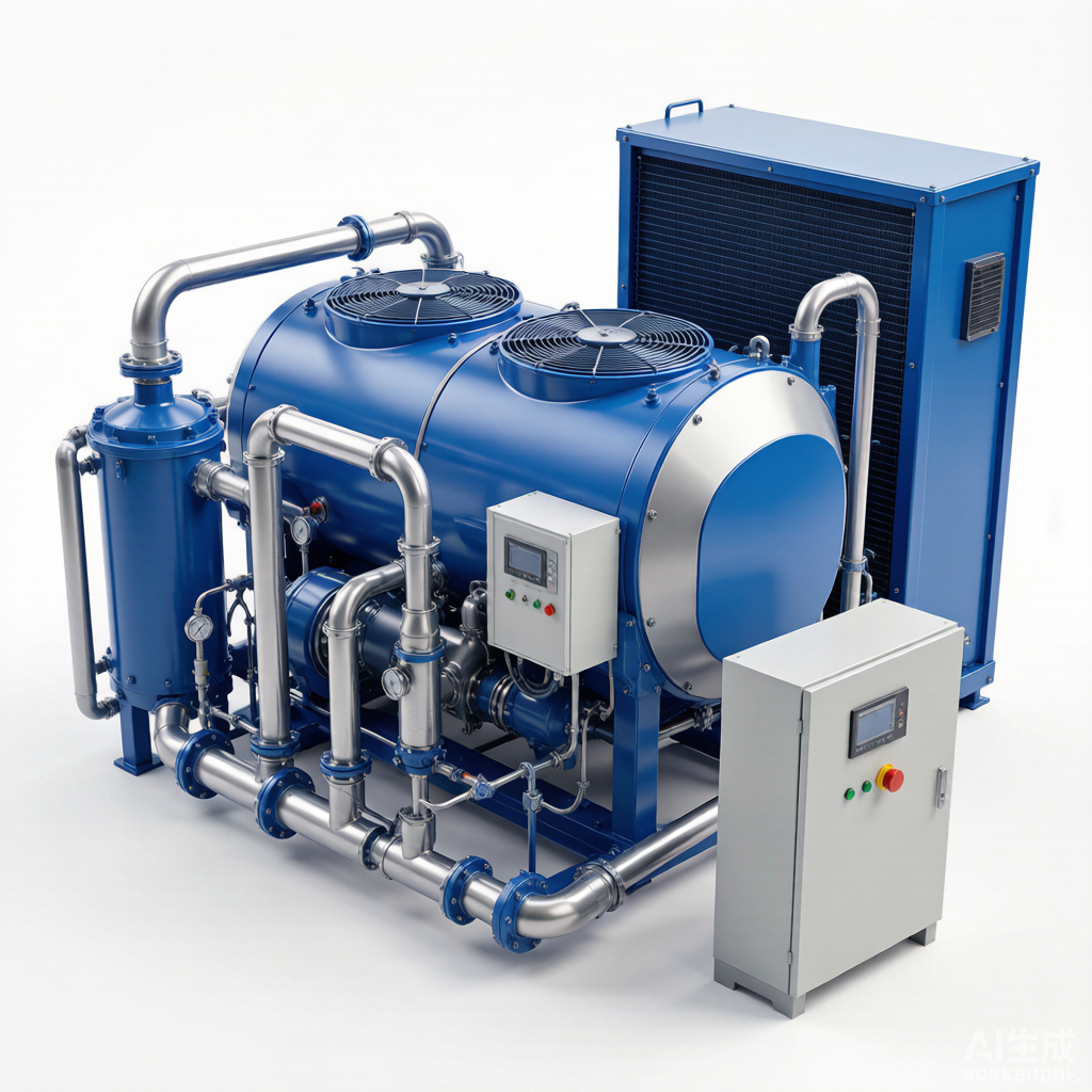
Figure: Centrifugal chiller plant showing compressor, condenser, evaporator, and auxiliary systems in a commercial HVAC installation
Centrifugal Chiller Fundamentals
Components
A centrifugal chiller is a vapor-compression refrigeration machine that uses a rotating impeller to impart kinetic energy to the refrigerant, converting it to pressure through diffusion. The four fundamental components form a closed thermodynamic loop:
- Compressor: The heart of the chiller, a single- or multi-stage centrifugal compressor accelerates refrigerant vapor through an impeller and then decelerates it in a diffuser, raising its pressure. The compressor is typically driven by an electric motor, though steam or gas turbine drives are used in large industrial installations.
- Condenser: A shell-and-tube heat exchanger where the hot, high-pressure refrigerant vapor from the compressor discharge is condensed to liquid by rejecting heat to cooling water from a cooling tower or to ambient air.
- Evaporator: A shell-and-tube heat exchanger where the liquid refrigerant evaporates at low pressure, absorbing heat from the chilled water loop that serves building or process cooling loads.
- Expansion Device: A variable-orifice or fixed-orifice device (often an electronic expansion valve or orifice plate) that throttles the high-pressure liquid refrigerant from the condenser down to evaporator pressure, initiating the flashing and cooling effect.
Refrigerant Types
The selection of refrigerant has a profound impact on chiller efficiency, safety, environmental compliance, and maintenance practices. Modern centrifugal chillers use the following refrigerants:
- R-134a: A hydrofluorocarbon (HFC) with zero ozone-depletion potential (ODP) that has been the workhorse of commercial centrifugal chillers for over two decades. It operates at positive pressure, is non-flammable, and is non-toxic. However, it has a high global warming potential (GWP) of 1,430, driving the transition to lower-GWP alternatives.
- R-1233zd: A hydrofluoroolefin (HFO) refrigerant with an ultra-low GWP of approximately 1 and zero ODP. It is a near-drop-in replacement for R-123 in low-pressure centrifugal chillers, offering comparable efficiency with a dramatically improved environmental profile. It is classified as A1 (non-flammable, low toxicity).
- R-514A: A zeotropic blend of R-1336mzz(Z) and R-1130(E) designed as a low-pressure replacement for R-123. It has a GWP of approximately 2 and zero ODP, making it an environmentally responsible option for new and retrofit low-pressure centrifugal chillers.
Performance Metrics
Evaluating and benchmarking chiller performance requires an understanding of the key efficiency metrics defined by AHRI Standard 550/590:
- COP (Coefficient of Performance): The ratio of cooling output (in kW) to electrical power input (in kW) at a specific operating condition. A modern centrifugal chiller typically achieves a COP of 5.0 to 7.0 at full-load AHRI conditions.
- IPLV (Integrated Part Load Value): A weighted average efficiency metric that reflects chiller performance across the range of part-load conditions most commonly encountered in real-world operation, with weights of 1% at 100% load, 42% at 75%, 45% at 50%, and 12% at 25%.
- NPLV (Non-Standard Part Load Value): Similar to IPLV but evaluated at non-standard operating conditions (e.g., different entering condenser water temperatures). NPLV is used to compare chillers designed for site-specific operating envelopes that differ from AHRI standard rating conditions.
Compressor Maintenance
Impeller Inspection and Cleaning
The centrifugal impeller is the most precision-machined component in the chiller. Even minor fouling or damage can significantly degrade aerodynamic performance and efficiency:
- Visual and Borescope Inspection: At every major service interval, use a borescope to inspect the impeller blades for erosion, pitting, cracks, and foreign object damage. Pay particular attention to the leading edges and blade tips where high-velocity particulate impact is most severe.
- Fouling Removal: Refrigerant-side fouling — typically oil carryover or oxidation deposits — reduces impeller aerodynamic efficiency and increases compressor power consumption. Clean the impeller with an approved solvent and soft brushes, avoiding abrasives that could alter blade surface finishes.
- Balance Verification: If the impeller has been cleaned, repaired, or if vibration readings suggest imbalance, verify dynamic balance per ISO 1940. Even a few grams of imbalance at operating speed (often 10,000+ rpm) can cause bearing damage and seal wear.
Bearing Health
Centrifugal chiller compressors rely on either sleeve (journal) bearings or, increasingly, magnetic bearings in oil-free designs. Monitoring bearing condition is critical to preventing catastrophic failure:
- Oil Analysis: For oil-lubricated bearings, draw oil samples at regular intervals (typically quarterly) and analyze for wear metals (iron, copper, tin, lead), viscosity, acid number, and water content. Rising trend lines in any wear metal warrant investigation before the next scheduled service.
- Vibration Trending: Collect vibration spectra at the compressor bearing housings and compare to baseline data. Increasing 1x running speed amplitude indicates imbalance; 2x amplitude suggests misalignment; subsynchronous components may indicate oil whirl or bearing instability.
- Magnetic Bearing Monitoring: In oil-free chillers with magnetic bearings, monitor the bearing position sensor outputs and backup bearing touchdown events. Frequent touch-downs indicate a control system or rotor dynamics problem that requires immediate attention.
Seal Inspection
The compressor shaft seal prevents refrigerant leakage from the high-pressure compressor housing to the atmosphere. Two seal designs are prevalent:
- Mechanical Seal: A face-type seal with rotating and stationary carbon or silicon-carbide faces, typically used in older or mid-range chillers. Inspect for face wear, elastomer degradation, and spring fatigue at every major overhaul. Leakage beyond a few drops per hour warrants seal replacement.
- Labyrinth Seal: A non-contacting seal with precision-machined fins that create a tortuous leakage path. Labyrinth seals are inherently more reliable but allow a controlled leak rate. Inspect the fins for rubbing damage caused by shaft excursions; if clearances have opened beyond OEM limits, the seal cartridge must be replaced.
Heat Exchanger Maintenance
Condenser Tube Cleaning
The condenser rejects heat from the refrigerant to the cooling water loop. Fouled condenser tubes raise the condensing pressure and compressor power consumption, directly degrading chiller efficiency:
- Mechanical Brushing: Use a tube cleaning system with nylon or brass brushes driven by water pressure to physically remove scale, biological slime, and sediment from the tube internals. This should be performed at least annually, or more frequently if the cooling tower water treatment program is inadequate.
- Chemical Cleaning: When mineral scale deposits are too tenacious for mechanical brushing alone, circulate a mild acid cleaning solution (e.g., dilute sulfamic or phosphoric acid with corrosion inhibitor) through the tubes. Neutralize and flush thoroughly before returning the chiller to service.
- Preventive Water Treatment: Implement a comprehensive cooling water treatment program that controls scale (via deposit inhibitors), corrosion (via passivating agents), and biological growth (via biocides and biodispersants). This is the single most effective measure to extend condenser tube cleaning intervals.
Evaporator Tube Inspection
The evaporator tubes absorb heat from the chilled water loop. While evaporator fouling is less common than condenser fouling (because the chilled water loop is typically closed), it still requires periodic inspection:
- Eddy Current Testing (ECT): Every 3-5 years, perform eddy current testing on a representative sample (or all) of the evaporator tubes to detect wall loss, pitting, and cracking that are not visible to the naked eye. ECT is the most reliable non-destructive method for identifying tubes at risk of failure.
- Tube Sheet and Waterbox Inspection: During waterbox removal, inspect the tube sheet for corrosion, pitting, and galvanic attack at the tube-to-tube-sheet joints. Re-roll or seal any tubes showing leakage at the joint.
Water Treatment
A properly managed water treatment program is essential to preserving heat exchanger integrity and maintaining chiller efficiency over the equipment life cycle:
- Scale Control: Prevent calcium carbonate and calcium sulfate deposition by maintaining appropriate cycles of concentration in the cooling tower, using scale inhibitors (phosphonates, polymers), and keeping the condenser approach temperature within target range.
- Corrosion Control: Apply corrosion inhibitors (azoles, molybdates, or ortho-phosphate programs) and monitor corrosion coupon rates. Acceptable mild steel corrosion rates are below 3 mils per year (mpy); copper rates should be below 0.5 mpy.
- Biological Control: Dose oxidizing (chlorine, bromine) and non-oxidizing biocides on an alternating schedule to prevent biofilm formation. Biofilm has a thermal conductivity four to five times lower than mineral scale, making it one of the most insidious causes of efficiency degradation.
Tube Plugging and Its Efficiency Impact
When a tube develops a leak or fails eddy current testing, it is often plugged rather than replaced. While plugging is an acceptable short-term repair, it has a quantifiable impact on performance:
- Heat Transfer Area Loss: Each plugged tube reduces the effective heat transfer surface area. A rule of thumb is that plugging up to 5% of tubes has a minor efficiency impact (less than 1-2% capacity loss), but exceeding 10% plugging significantly raises approach temperatures and compressor power.
- Flow Distribution: Plugging tubes in an uneven pattern can distort water flow distribution across the tube bundle, creating localized low-velocity zones that accelerate fouling and under-deposit corrosion in adjacent tubes.
Refrigerant Management
Leak Detection Methods
Refrigerant leakage represents both an environmental liability and a direct operating cost. A proactive leak detection program is essential for regulatory compliance and chiller efficiency:
- Electronic Leak Detectors: Use a heated-diode or infrared electronic leak detector to sniff for refrigerant around flanges, valve stems, shaft seals, and relief valve outlets. These devices can detect leaks as small as 0.1 oz/year and are the primary tool for routine surveys.
- Ultrasonic Detectors: Acoustic leak detectors sense the high-frequency hiss of escaping gas, even in noisy mechanical rooms. They are particularly useful for pinpointing leaks in insulated or hard-to-reach areas where electronic detectors may be difficult to maneuver.
- Bubble Testing: Apply a refrigerant-specific soap solution to suspected leak points and watch for bubble formation. This simple, low-cost method confirms leaks identified by electronic detectors and is effective for accessible connections and fittings.
Charge Verification
An undercharged or overcharged chiller cannot operate at design efficiency. Verifying the correct refrigerant charge requires measuring key thermodynamic parameters:
- Subcooling: Measure the liquid refrigerant temperature at the condenser outlet and compare it to the saturation temperature at condenser pressure. The difference (subcooling) should match the OEM specification, typically 5-15°F. Low subcooling indicates undercharge or a restriction; high subcooling suggests overcharge or non-condensables.
- Superheat: Measure the suction gas temperature at the compressor inlet and subtract the saturation temperature at evaporator pressure. Excessive superheat suggests undercharge or a faulty expansion device; insufficient superheat risks liquid flood-back to the compressor.
Refrigerant Recovery and Recycling
When a chiller requires service that opens the refrigerant circuit, the refrigerant must be recovered, recycled, or reclaimed in accordance with EPA Section 608 regulations (or equivalent local standards):
- Recovery: Use a certified recovery machine to transfer the refrigerant from the chiller to a DOT-approved recovery cylinder. The system must be evacuated to the EPA-required vacuum level before opening any connection.
- Recycling: Process the recovered refrigerant through a recycling unit that separates oil and removes moisture and acid via filter-driers. Recycled refrigerant may be returned to the same chiller (or another chiller with the same owner) but cannot be sold as reclaimed refrigerant.
- Reclamation: If the refrigerant fails purity specifications after recycling, send it to an EPA-certified reclamation facility where it is reprocessed to meet AHRI Standard 700 purity specifications and can be resold on the open market.
Control System Optimization
Setpoint Optimization
Modern centrifugal chillers are governed by sophisticated microprocessor-based controllers. Optimizing the setpoints can yield significant energy savings without compromising occupant comfort or process cooling:
- Chilled Water Reset: Rather than maintaining a fixed chilled water supply temperature (e.g., 44°F), implement a reset schedule that raises the setpoint as the building load decreases. Every 1°F increase in chilled water temperature can reduce chiller energy consumption by 1-2%, since the compressor faces a lower lift requirement.
- Condenser Water Reset: Lower the entering condenser water temperature setpoint when outdoor wet-bulb conditions permit, within the chiller manufacturer minimum limit. Reduced condensing pressure lowers compressor power, though excessively cold condenser water can cause surge and oil return problems in some designs.
Staging Multiple Chillers
In plants with two or more chillers, the sequencing logic determines how many machines operate at any given load. Proper staging is critical to plant-level efficiency:
- Optimal Loading: As a general rule, a single centrifugal chiller achieves its best efficiency between 40% and 80% of capacity. Staging logic should bring an additional chiller online when the lead machine exceeds approximately 80% load, rather than running one machine at 100% while others sit idle.
- Lead-Lag Rotation: Rotate the lead chiller periodically (e.g., weekly or based on run-hours) to equalize wear across the plant and ensure that standby equipment is exercised regularly, preventing seal dry-out and bearing degradation from prolonged inactivity.
Variable Primary Flow (VPF) Systems
In a conventional primary-secondary chilled water plant, the decoupler bypass line allows constant flow through chillers while variable-flow pumps serve the distribution loop. Variable primary flow (VPF) eliminates the secondary pumps and varies flow directly through the chiller evaporators:
- Energy Savings: VPF reduces pump energy by eliminating the secondary pump and allowing the primary pump speed to track actual load. Savings of 15-30% in pump energy are achievable compared to primary-secondary designs.
- Implementation Considerations: Chillers have minimum evaporator flow rates below which freeze protection and control stability are compromised. The VPF control sequence must incorporate a bypass valve that opens when the system flow approaches the minimum chiler flow threshold, and must coordinate chiller staging with flow rate changes to avoid rapid temperature swings.
Performance Benchmarking
Systematic performance benchmarking transforms raw operating data into actionable intelligence. By establishing baselines and tracking deviations, maintenance teams can detect degradation early, prioritize service activities, and justify capital investments in efficiency upgrades.
Daily Log Review
- Approach Temperatures: Monitor the evaporator approach (difference between leaving chilled water temperature and saturated refrigerant temperature) and condenser approach (difference between saturated refrigerant temperature and leaving condenser water temperature). Increasing approach values indicate heat exchanger fouling and should trigger cleaning.
- kW/ton: Calculate the chiller efficiency in kW per ton of cooling (kW/ton = compressor kW / tons of cooling). Compare daily readings to the baseline established at commissioning. A 5-10% increase warrants investigation; a 15-20% increase typically indicates a correctable maintenance issue.
Trend Analysis and Degradation Detection
- Baseline Establishment: Record performance data under steady-state conditions at known load points (e.g., 25%, 50%, 75%, 100%) immediately after a major cleaning or overhaul. This becomes the reference baseline for all subsequent comparisons.
- Degradation Curves: Plot approach temperatures and kW/ton versus time or operating hours. A consistent upward slope — even if readings remain within alarm thresholds — indicates progressive fouling or mechanical wear that should be scheduled for correction before it becomes a failure.
- Seasonal Normalization: Normalize performance data for varying entering condenser water temperatures and load conditions before drawing conclusions. Apparent degradation may simply reflect seasonal changes in tower water temperature or building load profile.
Typical Performance Benchmark Values
| Parameter | Good | Acceptable | Action Required |
|---|---|---|---|
| Evaporator Approach (°F) | < 2.0 | 2.0 – 3.0 | > 3.0 |
| Condenser Approach (°F) | < 1.5 | 1.5 – 3.0 | > 3.0 |
| kW/ton at Full Load | < 0.55 | 0.55 – 0.65 | > 0.65 |
| kW/ton at Part Load (50%) | < 0.40 | 0.40 – 0.50 | > 0.50 |
| Oil Pressure Differential (psi) | 15 – 25 | 10 – 30 | < 10 or > 30 |
| Compressor Discharge Temp (°F) | < 195 | 195 – 210 | > 210 |
| Refrigerant Moisture (ppm) | < 20 | 20 – 50 | > 50 |
| Oil Moisture (ppm) | < 50 | 50 – 100 | > 100 |
| Vibration (in/s peak) | < 0.1 | 0.1 – 0.2 | > 0.2 |
| Condenser Fouling Penalty (%) | < 2 | 2 – 5 | > 5 |
Source: Compressor Maintenance Forum