
Centrifugal Compressor Maintenance Guide
By Nick Li · August 10, 2026 · Technical Articles
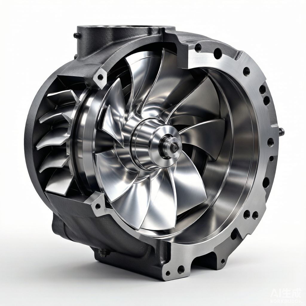
Figure: Cutaway view of a centrifugal compressor showing internal components
Centrifugal Compressor Operating Principles
Centrifugal compressors are dynamic machines that raise gas pressure by converting kinetic energy into static pressure through a continuous flow process. Unlike positive displacement compressors, centrifugal units handle large volumes of gas at relatively stable pressures, making them indispensable in refineries, petrochemical plants, and natural gas pipeline stations. Understanding the aerodynamic and thermodynamic principles governing their operation is the foundation of any effective maintenance program.
Impeller
The impeller is the heart of a centrifugal compressor. It consists of a rotating disk fitted with curved blades that accelerate the incoming gas outward from the eye of the impeller to its periphery. As the impeller spins at high speed—often between 3,000 and 30,000 RPM depending on the application—it imparts both velocity and a limited amount of pressure energy to the gas. The geometry of the impeller blades (backward-curved, radial, or forward-curved) directly influences the compressor’s efficiency, pressure ratio, and stable operating range. Multi-stage compressors use a series of impellers mounted on a single shaft, each stage incrementally raising the gas pressure.
Diffuser
After leaving the impeller, the high-velocity gas enters the diffuser, where the flow passage gradually widens. This increasing cross-sectional area decelerates the gas, converting the kinetic energy imparted by the impeller into static pressure—a process governed by Bernoulli’s principle. Vaned diffusers use fixed or adjustable blades to guide the flow and enhance this conversion, while vaneless diffusers offer a wider operating range at the expense of peak efficiency. The diffuser is critical to overall compressor performance; fouling, erosion, or dimensional changes in this component can significantly degrade the pressure ratio and efficiency.
Inlet Guide Vanes
Inlet guide vanes (IGVs) are adjustable blades positioned upstream of the first-stage impeller. They impart a controlled pre-swirl to the incoming gas, altering the velocity triangle at the impeller inlet. By adjusting the IGV angle, operators can regulate the compressor’s flow capacity and surge margin without changing the rotational speed. IGVs are a primary means of capacity control in variable-load applications, and their proper functioning is essential for maintaining stable operation across a wide range of process conditions.
Volute Casing
The volute casing collects the gas exiting the diffuser and channels it toward the discharge nozzle. The volute’s spiral-shaped passage gradually increases in area around the circumference, further decelerating the flow and converting residual kinetic energy into static pressure. The volute also serves as the pressure-containing boundary of the compressor and must withstand the full discharge pressure and temperature. Improper volute design or internal leakage at the casing joints can cause circumferential pressure distortion, leading to increased bearing loads and reduced efficiency.
Gas Velocity Conversion to Pressure
The fundamental principle underlying centrifugal compressor operation is the progressive conversion of gas velocity into static pressure. The impeller accelerates the gas to high velocities—often exceeding 300 m/s at the blade tip—while the diffuser and volute systematically decelerate the flow. In a well-designed multistage compressor, roughly half of the total pressure rise occurs within the impeller itself, with the remainder generated in the diffuser and volute. This two-step energy conversion—first to kinetic energy, then to static pressure—is the defining characteristic that distinguishes dynamic compressors from positive displacement machines.
Key Components and Inspection Points
A structured inspection program targeting critical components is essential for preventing unplanned shutdowns and extending compressor service life. The following sections outline the primary components, their failure mechanisms, and recommended inspection techniques.
Impeller
- Erosion: Inspect blade surfaces and leading edges for material loss caused by high-velocity particle impact or liquid droplet impingement. Use dye penetrant testing to detect surface-connected cracks. Measure blade thickness at designated points and compare against baseline records to track erosion rates over time.
- Corrosion: Examine the impeller eye, hub, and blade root areas for pitting, rust, and chemical attack. Stainless steel and titanium impellers resist corrosion but are not immune to chloride-induced stress corrosion cracking. Document all findings with photographs and dimensional measurements.
- Balance checks: Perform high-speed balancing after any repair or blade replacement. An unbalanced impeller generates excessive synchronous vibration that can destroy bearings and seals. The residual unbalance should meet API 617 acceptance criteria—typically 4W/N oz-in for flexible rotors, where W is the journal weight in pounds and N is the operating speed in RPM.
Bearings
- Vibration analysis: Monitor both radial and axial vibration using proximity probes mounted at 90-degree offsets on each bearing. Track overall vibration amplitude, 1X (synchronous), 2X, and subsynchronous frequency components. Rising 1X amplitude often indicates unbalance or misalignment, while subsynchronous components may signal oil whirl or bearing instability.
- Temperature monitoring: Install RTD or thermocouple sensors in the bearing babbitt layer to measure metal temperature directly. Babbitt temperatures exceeding 95°C (203°F) warrant immediate investigation, as they indicate inadequate lubrication, overload, or imminent bearing failure. Trend the temperature data to identify gradual deterioration before alarm thresholds are reached.
- Lubrication: Maintain the correct oil viscosity grade and supply pressure as specified by the manufacturer. Verify that the oil flow rate to each bearing meets design requirements. Inspect the bearing surfaces during scheduled overhauls for signs of wiping, babbitt fatigue, and embedded contaminants. Analyze oil samples for wear metals—elevated tin and copper levels indicate babbitt degradation.
Seals
Sealing systems prevent the escape of process gas along the rotor shaft. Two primary technologies dominate centrifugal compressor applications: dry gas seals and labyrinth seals. Each type has distinct maintenance requirements and failure characteristics.
Dry gas seals use a grooved rotating ring facing a stationary carbon ring, with a thin film of clean barrier gas maintaining separation between the faces. They offer extremely low leakage rates and eliminate the need for a sealing oil system. However, dry gas seals are sensitive to contamination—dirt, liquids, or oil in the seal gas supply can destroy the sealing faces within hours. Maintenance requires clean gas filtration, monitoring of seal gas differential pressure, and periodic verification of secondary O-ring integrity. Seal replacement typically occurs every 36 to 60 months, depending on operating conditions.
Labyrinth seals consist of a series of precision-machined teeth that create tortuous paths for gas leakage. They are robust, tolerant of contamination, and suitable for lower-pressure applications. However, labyrinth seals have higher leakage rates and cannot contain gas as effectively as dry gas seals. Inspection focuses on tooth tip clearance—excessive clearance from rub damage increases leakage dramatically. Measure clearances with feeler gauges or lead wire impressions during overhauls and replace seals when clearances exceed manufacturer tolerances by more than 50%.
Inlet Guide Vanes
The IGV adjustment mechanism typically consists of a set of aerodynamically shaped blades connected via linkage arms to a unison ring. An actuator—pneumatic, hydraulic, or electric—rotates the ring to change all blade angles simultaneously. Inspection points include blade bushing wear, linkage pin condition, unison ring smoothness, and actuator calibration. Worn bushings introduce play that causes individual blades to deviate from the commanded angle, degrading aerodynamic performance and potentially inducing stall. Lubricate the linkage pivot points per the manufacturer schedule and verify that the actuator position feedback matches the actual blade angle within tolerance.
Common Failure Modes
Centrifugal compressors are subject to several well-documented failure modes. Recognizing the early warning signs and understanding the root causes enables maintenance teams to take corrective action before catastrophic damage occurs.
Surge and Stall
Surge is the most destructive phenomenon in centrifugal compressor operation. It occurs when the flow through the compressor drops below a critical minimum, causing the gas to momentarily reverse direction. This flow reversal produces violent pressure pulsations, high-amplitude vibration, and rapid temperature rise that can destroy internal components within seconds. Causes include sudden process demand changes, blocked discharge paths, and malfunctioning antisurge control valves. The primary cause is operating the compressor to the left of its surge control line on the performance map.
Stall, by contrast, is a localized flow separation that occurs on individual impeller blades or diffuser vanes. It precedes full surge and manifests as a distinct subsynchronous vibration component. While less immediately destructive than surge, persistent stall degrades efficiency and accelerates blade fatigue.
Antisurge control systems protect the compressor by continuously monitoring flow and discharge pressure. When the operating point approaches the surge line, the controller opens a recycle (antisurge) valve that returns discharge gas to the suction, increasing flow through the compressor. Modern antisurge controllers use predictive algorithms that account for molecular weight changes, speed variations, and process disturbances. Regular testing of the antisurge valve stroke time and controller response is critical—the valve must reach full open position within 1 to 2 seconds to prevent surge during transient events.
Bearing Failure
Bearing failures in centrifugal compressors are rarely sudden; they develop over time and leave characteristic signatures in the vibration spectrum. Vibration spectrum analysis is the primary diagnostic tool for detecting bearing distress before failure occurs. Key indicators include:
- 1X frequency increase: Synchronous vibration growth often indicates rotor unbalance, shaft bow, or thermal distortion. A sudden step change may indicate blade loss or scale detachment from the impeller.
- 2X frequency: A prominent 2X component suggests misalignment between the compressor and driver shafts, or a cracked shaft. Monitor the phase relationship between the 1X and 2X components to differentiate between these causes.
- Subsynchronous frequency: Oil whirl produces a vibration component at 0.42 to 0.48 times the running speed. If left uncorrected, oil whirl can escalate into oil whip—a self-excited vibration that persists even after the triggering condition is removed.
- High-frequency broadband: Babbitt fatigue and spalling generate broadband vibration energy in the 1 to 20 kHz range. Accelerometers mounted on the bearing housing can detect this distress mode, which proximity probes may miss.
Seal Leakage
Seal leakage detection depends on the seal type. For dry gas seals, primary seal gas leakage is monitored via the vent flow rate and pressure. A rising vent flow trend indicates seal face wear or contamination. Secondary seal leakage—detected by gas detection at the bearing cavity—signals O-ring failure. For labyrinth seals, increased suction-to-discharge leak paths manifest as reduced compressor efficiency and elevated suction temperature. Replacement of dry gas seal cartridges requires clean-room conditions, specialized tooling, and strict adherence to the manufacturer’s torque sequence. Labyrinth seal replacement is less complex but requires precise clearance setup to avoid rotor rubs on startup.
Impeller Damage
Impeller damage takes two primary forms: erosion from liquid droplets and erosion from solid particle impact. Droplet erosion occurs when liquid carryover from upstream separators or condensation enters the compressor at high velocity. The repeated impact of liquid droplets on the blade leading edge creates a characteristic scalloped wear pattern that progressively thins the blade. Particle impact erosion results from entrained solids—rust, catalyst fines, or pipeline scale—striking the impeller at high relative velocity. This damage concentrates at the blade outer diameter and exducer tips.
Preventive measures include upgrading upstream separator efficiency, installing inlet filters, and maintaining gas temperature above the dew point. When blade thickness measurements fall below the manufacturer’s minimum threshold, the impeller must be replaced or refurbished by a qualified repair facility. Never attempt to weld-repair high-speed impellers without full stress relief, re-balance, and overspeed testing per API 617.
Maintenance Best Practices
A disciplined maintenance program extends compressor life, improves reliability, and reduces lifecycle costs. The following practices represent industry consensus for centrifugal compressor care.
Alignment Verification (Hot vs. Cold)
Thermal growth during operation shifts the relative positions of the compressor, gearbox, and driver shafts. Cold alignment that appears perfect at ambient temperature may be significantly misaligned at operating temperature. Two approaches address this challenge. The first method calculates the expected thermal expansion of each casing based on material coefficients and operating temperatures, then intentionally sets the cold alignment offset to compensate. The second method uses laser alignment tools with thermal targets, and a hot alignment check is performed after the machine reaches steady state. Both methods require accurate temperature measurements of the bearing housings, casings, and support feet. Document the hot and cold alignment data for each machine and review trends to detect foundation settling or pipe strain development.
Rotor Balancing
Rotor balancing is essential after any intervention that disturbs the rotating assembly—impeller replacement, coupling change, or shaft repair. Low-speed balancing in a balancing machine corrects static and dynamic unbalance by adding or removing material at designated correction planes. However, low-speed balancing does not account for the dynamic behavior of the rotor at operating speed, where flexible rotor modes may amplify residual unbalance. For flexible rotors—typically those operating above their first critical speed—high-speed balancing at operating speed in a vacuum chamber or spin pit is recommended. Always perform an overspeed test at 110 to 120 percent of operating speed after balancing to verify structural integrity and confirm that the rotor does not change balance state under centrifugal load.
Oil System Maintenance
The oil system is the lifeblood of the compressor. Clean, cool, and properly pressurized lubricating oil is essential for bearing and seal longevity. Key maintenance tasks include:
- Filter replacement: Replace oil filter elements when the differential pressure reaches the manufacturer-recommended change-out point, typically 1.5 to 2.0 bar. Never bypass a clogged filter—switch to the standby filter element and replace the spent element promptly.
- Oil cooler cleaning: Tube-side fouling reduces heat transfer capacity, causing rising oil temperatures. Clean the cooler tubes annually or when the oil-to-cooling-water temperature differential exceeds design values. Inspect tubes for corrosion and wall thinning using eddy current testing.
- Reservoir maintenance: Drain water and sediment from the reservoir bottom monthly. Inspect the reservoir interior for rust and coating degradation during major overhauls. Keep the reservoir breather desiccant fresh to prevent moisture ingress.
- Oil sampling: Draw oil samples from the properly designated sampling valves—never from the drain port. Analyze for viscosity, water content, particle count, acid number, and wear metals. Establish trend baselines and set alarm limits based on ISO 4406 cleanliness codes.
Performance Testing and Trending
Regular performance testing tracks the compressor’s aerodynamic health over time. Measure suction and discharge pressure, temperature, flow rate, and speed under steady-state conditions. Calculate the head, efficiency, and polytropic exponent, then compare the results to the baseline performance curve. Degradation in head or efficiency typically indicates internal fouling, seal deterioration, or impeller damage. Plot the performance data on a trend chart and review it monthly. A 2 to 3 percent efficiency decline warrants investigation; a 5 percent decline typically justifies a planned shutdown for internal inspection and cleaning.
Troubleshooting Quick Reference
The following table provides a quick reference for common symptoms, their probable causes, and recommended corrective actions. Use this table as a starting point for troubleshooting, and always confirm the diagnosis with appropriate diagnostic data before undertaking major repairs.
| Symptom | Probable Cause | Corrective Action |
|---|---|---|
| High vibration at 1X frequency | Rotor unbalance; thermal bow; impeller fouling | Perform field balancing; inspect and clean impeller; verify warm-up procedure |
| High vibration at 2X frequency | Shaft misalignment; loose coupling; cracked shaft | Realign coupling; inspect coupling bolts; perform shaft NDE examination |
| Subsynchronous vibration (0.42–0.48X) | Oil whirl; bearing instability | Verify oil viscosity and supply pressure; inspect bearing clearance and preload; consider tilt-pad bearing upgrade |
| High bearing temperature | Inadequate oil flow; oil degradation; bearing overload | Check oil supply pressure and flow; replace oil; inspect bearing surface for wiping and fatigue |
| Surge events during transients | Antisurge valve too slow; controller tuning; process disturbance | Test and reduce valve stroke time; retune controller; widen surge control margin |
| Declining compressor efficiency | Internal fouling; seal wear; impeller erosion | Schedule wash or overhaul; replace seals; inspect impeller for erosion and measure blade thickness |
| Dry gas seal leakage increase | Seal face contamination; O-ring degradation; secondary seal failure | Verify seal gas filtration; replace seal cartridge; inspect and replace O-rings |
| Abnormal discharge temperature | Internal recirculation; valve leakage; insufficient cooling | Inspect check valves and antisurge valve; verify intercooler performance; check internal seal clearances |
| Oil carryover in seal gas | Degraded oil separator; foaming; excessive oil level | Replace coalescing filter element; check oil anti-foam additive; verify reservoir oil level |
| Compressor will not start | Interlock trip; low oil pressure; seal gas pressure low | Check trip relay and alarm panel; verify auxiliary oil pump operation; confirm seal gas supply pressure and differential |
Source: Compressor Maintenance Forum