
Common Faults and Troubleshooting for Screw Compressors
By Nick Li · August 10, 2026 · Technical Articles
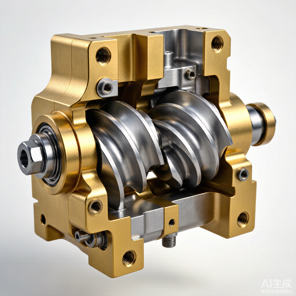
Figure: Cross-sectional view of a twin-screw compressor showing interlocking male/female rotors, discharge port, slide valve capacity control, and oil injection pathways
Working Principle of Screw Compressors
The screw compressor is a positive displacement rotary machine that has become the dominant compressor type in medium-capacity refrigeration and compressed air applications, ranging from 30 to 1500 kW. Its widespread adoption is attributable to several inherent advantages over reciprocating compressors: continuous compression without pulsation, fewer moving parts, higher reliability, and tolerance for liquid slugging. Understanding the fundamental operating principle is essential for effective troubleshooting and preventive maintenance.
Interlocking Male and Female Rotors
The heart of the screw compressor consists of a pair of helical rotors mounted on parallel shafts within a precision-machined casing. The male rotor typically has 4 or 5 convex lobes, while the female rotor has 6 or 7 concave flutes. The rotors are manufactured to micron-level tolerances, with running clearances typically between 0.025 and 0.075 mm (0.001 to 0.003 inches). These tight clearances are maintained by precision timing gears or, in oil-flooded designs, by direct contact between the rotors with oil film separation.
- Drive Configuration: The male rotor is typically the driven rotor, directly coupled to the motor. The female rotor is driven by the male rotor through the intermeshing lobes, with the timing gears ensuring synchronization. The male rotor typically rotates at 1500-3600 RPM for 50/60 Hz motors, though variable speed drives extend this range.
- Compression Principle: As the rotors rotate, the inter-lobe spaces at the suction end open to the inlet port, drawing in gas. As rotation continues, the meshing lobes trap a volume of gas and progressively reduce its volume as the trapped pocket moves axially toward the discharge end. The built-in volume ratio (Vi) typically ranges from 2.2 to 5.0, depending on the application pressure ratio.
Oil Injection System: Sealing, Cooling, and Lubrication
In oil-flooded screw compressors, a significant quantity of oil (3-15% by volume of the displaced gas) is injected directly into the compression chamber. The oil serves three critical functions simultaneously:
- Sealing: Oil fills the microscopic clearance gaps between the rotors and between the rotors and the casing, dramatically reducing internal gas leakage and improving volumetric efficiency from approximately 70% (oil-free) to over 90% (oil-flooded).
- Cooling: Oil absorbs the heat of compression, limiting the discharge temperature to 70-100°C (158-212°F). Without oil cooling, discharge temperatures could exceed 200°C, causing thermal expansion sufficient to eliminate running clearances and seize the rotors.
- Lubrication: The oil film prevents metal-to-metal contact between the rotors and lubricates the bearings, shaft seals, and capacity control mechanisms. The oil also provides corrosion protection for internal surfaces.
Three Phases of Compression
Each compression cycle consists of three distinct phases occurring simultaneously in different inter-lobe chambers:
- Suction Phase: As a rotor lobe un-meshes from the corresponding flute at the suction end, the expanding inter-lobe volume creates a partial vacuum that draws gas in through the suction port. Filling continues until the lobe re-engages with the next flute, trapping a discrete volume of gas. The suction process is continuous and pulse-free, unlike the intermittent suction of reciprocating compressors.
- Compression Phase: The trapped gas pocket is transported axially along the rotors as they continue to rotate. The volume of the pocket progressively decreases as the male lobe intrudes further into the female flute space. Oil injected during this phase absorbs heat and seals the clearance gaps. The compression is internal; the discharge port design determines when the compressed gas is released.
- Discharge Phase: When the leading edge of the trapped pocket reaches the discharge port (typically a triangular or axial port at the discharge end), the compressed gas-oil mixture is expelled into the discharge plenum. Ideally, the internal pressure at the moment of port opening matches the discharge line pressure (no under-compression or over-compression losses). The gas-oil mixture then passes to an oil separator before the gas exits to the system.
Bearing Burnout
Bearing failures are among the most serious and costly faults in screw compressors, as they often result in catastrophic rotor-to-rotor or rotor-to-casing contact, necessitating a complete compressor rebuild or replacement. Both radial (journal or roller) and thrust bearings are critical to maintaining rotor positioning within micron-level tolerances.
Symptoms
- Abnormal Noise: A distinct rumbling, grinding, or squealing sound emanating from the compressor housing, often initially intermittent and load-dependent, becoming continuous as the damage progresses.
- Excessive Vibration: Vibration levels exceeding the manufacturer’s alarm threshold (typically 7.1 mm/s RMS per ISO 10816-3 for medium machines). Vibration spectrum analysis typically shows elevated amplitudes at bearing defect frequencies (BPFO, BPFI, BSF, FTF).
- Elevated Bearing Temperature: Bearing housing temperatures exceeding 80°C (176°F) or a sudden 10-15°C rise above the normal operating baseline, indicating loss of lubrication or incipient bearing damage.
- Metal Particles in Oil: Abnormal concentrations of bearing metal alloy elements (copper, lead, tin) in spectrographic oil analysis, or visible metallic flakes in the oil filter or sight glass.
Causes and Solutions
- Foreign Matter in Oil: Cause: Abrasive particles (silica, metal wear debris, carbon deposits) enter the bearing clearance, causing three-body abrasive wear. Particles smaller than the minimum oil film thickness (typically 1-5 microns) are the most damaging. Solution: Improve oil filtration from nominal 10-micron to absolute 3-micron rating. Conduct root cause analysis to identify particle ingress source. Flush the entire lubrication system with clean oil before restarting.
- Low Oil Pressure: Cause: Insufficient oil supply to bearings due to oil pump failure, clogged oil filter, broken oil line, or excessive internal leakage through worn bearing clearances. The minimum required oil pressure is typically 0.5-1.0 bar (7-15 psi) above compressor discharge pressure for oil-flooded designs. Solution: Verify oil pump operation and pressure setpoint. Replace clogged filters. Check for internal oil circuit restrictions. Install differential pressure alarms to detect filter clogging before it affects bearing supply pressure.
- Oil Degradation: Cause: Lubricant oxidation and thermal breakdown due to high discharge temperatures, moisture contamination, or extended oil service intervals. Degraded oil loses viscosity, reducing the load-carrying capacity of the oil film. Solution: Regular oil sampling and analysis (every 2000 operating hours). Replace oil when total acid number (TAN) increases by 0.5 mg KOH/g above new oil baseline. Maintain discharge temperature below manufacturer’s limit (typically 100°C or 212°F). Use synthetic oils with higher thermal stability for severe-duty applications.
Rotor Damage
The precision rotors are the most expensive components in a screw compressor, often representing 40-60% of the total compressor cost. Rotor damage ranges from superficial coating wear to catastrophic mechanical failure, and most rotor damage is preventable through proper system design and maintenance practices.
Symptoms
- Reduced Capacity: Gradual or sudden loss of compressor capacity (flow rate at a given discharge pressure). A 0.1 mm increase in rotor-to-rotor clearance can reduce volumetric efficiency by 2-5%.
- Abnormal Operating Sounds: High-frequency metallic scraping or clicking sounds, distinct from normal gas flow and oil injection noise. The sound typically synchronizes with the lobe-passing frequency (rotor speed × number of lobes).
- Increased Power Consumption: A rise in specific power (kW per CFM or kW/RT) without a corresponding change in operating conditions, indicating increased internal leakage requiring more input power to maintain output.
Causes and Solutions
- Foreign Object Ingestion: Cause: Solid debris (weld slag, pipe scale, broken valve parts, filter media fragments) enters the compressor suction and passes through the rotor meshing zone, causing scoring, pitting, or fracture of lobe surfaces. Solution: Install high-quality suction strainers or filters. Conduct thorough system cleaning and flushing during commissioning. Implement a formal pipeline cleanliness verification procedure before connecting any compressor to new or modified piping.
- High Inlet Temperature: Cause: Excessive suction gas temperature causes thermal expansion of the rotors, reducing running clearances. When the expansion exceeds the designed clearance, rotor-to-rotor or rotor-to-casing contact occurs. Solution: Verify that the suction temperature does not exceed the manufacturer’s specification (typically 50°C or 122°F maximum for refrigeration compressors). Check operation of suction line accumulators and liquid injection cooling systems if installed.
- Compression Ratio Exceeding Design Limit: Cause: Operating at a pressure ratio significantly higher than the design Vi (built-in volume ratio) causes over-compression. The internal pressure at the discharge port exceeds the discharge line pressure, resulting in a sudden pressure equalization that generates shock waves and excessive rotor thrust loads. Solution: Operate within the manufacturer’s specified pressure ratio envelope. For applications with wide pressure variation, consider a variable Vi compressor with adjustable slide valve or variable speed drive to match the Vi to operating conditions.
Abnormal Vibration and Noise
Vibration analysis is one of the most powerful diagnostic tools for screw compressor condition monitoring. By trending vibration signatures over time and analyzing frequency spectra, technicians can identify developing faults weeks or months before they cause operational failure.
Shaft Wobble (Runout)
- Cause: Bent shaft due to improper handling during maintenance, uneven thermal growth, or bearing seat wear causing eccentric rotation. Shaft runout exceeding 0.025 mm (0.001 inch) TIR (Total Indicator Reading) can cause significant vibration and accelerated seal wear. Solution: Measure shaft runout with a dial indicator at multiple axial positions. If runout exceeds specification, the shaft must be straightened or replaced. Always support rotors at designated lifting points during handling and storage.
Coupling Deterioration
- Cause: Flexible coupling wear (rubber element degradation, gear tooth wear, disc pack fatigue) introduces misalignment and torsional vibration. A worn coupling can produce vibration at 1×, 2×, and 3× running speed, with possible harmonics. Solution: Perform laser alignment to within 0.05 mm (0.002 inch) parallel and 0.05 mm/100 mm angular offset. Replace worn coupling elements. For gear-type couplings, verify adequate lubrication and check for tooth wear patterns indicating misalignment.
Bearing Wear
- Cause: Progressive wear of rolling element bearings due to fatigue spalling, brinelling (from shock loads or static vibration), or electrical pitting (from shaft currents). Bearing defect frequencies appear as non-synchronous peaks in the vibration spectrum. Solution: Establish baseline vibration readings at bearing locations in three axes (horizontal, vertical, axial) during commissioning. Set alarm thresholds at 2× baseline and shutdown thresholds at 3× baseline per ISO 10816-3. Replace bearings when defect frequency amplitudes show an accelerating trend.
Low Oil Pressure
Adequate oil pressure is critical to screw compressor reliability. Low oil pressure can lead to bearing failure, rotor contact, and complete compressor seizure within minutes. Most compressor control systems include low oil pressure safety trips; however, intermittent low-pressure conditions during startup or load changes may cause cumulative damage before a hard trip occurs.
Insufficient Oil Quantity
- Cause: Oil level below the minimum mark in the separator sight glass due to oil carryover, system leaks, or incomplete charging during oil change. The oil separator element typically retains up to 1 liter of oil that is lost when the element is changed. Solution: Check oil level at normal operating temperature with the compressor running (if the manufacturer specifies a running level check). Top up with the specified oil grade to the correct level. Investigate and repair system oil leaks. Monitor oil consumption rate; consumption exceeding 10% of the total charge per month indicates excessive carryover.
Poor Oil Quality
- Cause: Viscosity loss due to fuel dilution, thermal cracking, or use of incorrect oil grade. Contaminants including water, acids, and solid particles degrade lubricating properties. Solution: Test oil viscosity at 40°C and compare to the specification (typically ISO VG 46 or 68 for screw compressor oil). If viscosity is more than 10% below specification or if the viscosity index has degraded significantly, replace the oil. Implement regular oil analysis to trend degradation before it reaches critical levels.
Clogged Oil Path and Oil Pump Wear
- Clogged Oil Path: Cause: Accumulation of varnish, sludge, or debris in oil galleries, filter housings, and heat exchanger passages. A partially clogged oil cooler can cause a 1-2 bar (15-30 psi) pressure drop that reduces the net oil supply pressure. Solution: Clean or replace oil filters on schedule. Periodically inspect and clean oil cooler tubes. Use high-quality synthetic oil with good oxidation resistance to minimize varnish formation. Consider installing a kidney-loop filtration system for continuous oil polishing.
- Oil Pump Wear: Cause: Internal wear of the oil pump gears, vanes, or rotors reduces volumetric efficiency and discharge pressure. External gear pumps typically show pressure degradation of 0.5-1 bar per 10,000 hours of operation. Solution: Test oil pump delivery pressure against the specification at rated speed. If pump delivery is below specification after adjusting the pressure regulator, the pump should be rebuilt or replaced. Install a pressure gauge at the pump discharge for trending.
High Discharge Pressure and Temperature
Elevated discharge conditions are among the most common operating faults and, if left uncorrected, accelerate oil degradation, reduce volumetric efficiency, and increase the risk of compressor damage. Systematic diagnosis of the root cause is essential, as multiple contributing factors often interact.
Excess Refrigerant Charge
- Cause: In refrigeration systems, overcharging results in liquid refrigerant entering the compressor suction, reducing the effective swept volume as the liquid occupies space normally available for gas. The compressor must work against higher discharge pressure due to flooded condenser conditions. Solution: Recover refrigerant to achieve the correct charge as indicated by proper subcooling (typically 5-8 K or 9-14°F) and a clear sight glass. Verify charge by measuring subcooling at the condenser outlet, not solely by sight glass indication.
Faulty Check Valve
- Cause: A leaking or stuck-open discharge check valve allows high-pressure gas to flow backward into the compressor during the unloaded or stopped condition. On restart, the compressor must start against reverse pressure, causing high starting current and immediate high discharge temperature. Solution: Test the check valve by monitoring the discharge line temperature immediately downstream of the valve. A hot pipe during compressor shutdown indicates leakage. Replace the check valve if it fails to seal. Consider a dual check valve arrangement for critical applications.
Air or Non-condensable Gas in System
- Cause: Air ingress through low-pressure side leaks, incomplete evacuation before charging, or decomposition of refrigerant and oil at high temperatures. Non-condensables accumulate in the condenser, reducing the effective heat transfer area and elevating the condensing pressure. Solution: Purge non-condensables from the highest point in the condenser (where gases collect). The presence of non-condensables is indicated by a condensing pressure higher than the saturation pressure corresponding to the measured liquid line temperature. Locate and repair low-side leaks. Perform a standing vacuum decay test to verify system tightness after repair.
Poor Cooling (Condenser or Oil Cooler)
- Cause: Fouled condenser or oil cooler surfaces (air-cooled: dirt, leaves, blocked airflow; water-cooled: scale, biological fouling, sediment). Reduced cooling capacity forces higher condensing and oil temperatures. Solution: Clean air-cooled condenser coils with compressed air or chemical coil cleaner (follow manufacturer’s recommendations to avoid fin damage). For water-cooled systems, perform periodic tube cleaning (mechanical brushing or chemical descaling). Verify cooling tower operation and water treatment program. Check for proper condenser fan operation and rotation.
Preventive Maintenance Schedule
A structured preventive maintenance program is the most effective strategy for maximizing screw compressor reliability and service life. The following schedule represents industry best practice for oil-flooded screw compressors in typical industrial service. Adjust intervals based on operating conditions, criticality, and manufacturer’s specific recommendations.
| Interval | Maintenance Task | Details |
|---|---|---|
| Daily | Visual Inspection | Check oil level, discharge temperature, discharge pressure, suction pressure, vibration (subjective), unusual noise, oil/refrigerant leaks. |
| Weekly | Oil Filter Differential | Record oil filter differential pressure. Schedule replacement when ΔP exceeds 1 bar (15 psi) across the filter. |
| Monthly | Vibration Monitoring | Collect vibration readings at bearing locations. Trend overall levels (mm/s RMS) and compare to ISO 10816-3 limits. |
| Quarterly | Oil Sampling & Analysis | Send oil sample for spectrographic analysis. Check viscosity, TAN, moisture content, particle count (ISO 4406). Compare to baseline. |
| Semi-Annual | Electrical Checks | Megger test motor windings. Check contactor contacts. Verify control setpoints and safety trip settings. Calibrate pressure/temperature sensors. |
| Annual | Comprehensive Inspection | Replace oil, oil filter, separator element, and air filter (if applicable). Inspect check valve, minimum pressure valve, and capacity control mechanism. Clean oil cooler and condenser. |
| Biennial | Coupling & Alignment | Inspect flexible coupling element for wear. Perform precision laser shaft alignment. Check rotor end clearance per manufacturer spec. |
| 5-Year | Major Overhaul | Disassemble compressor for internal inspection. Measure bearing clearances and replace all bearings. Inspect rotors for coating condition. Replace shaft seal. Renew all gaskets and O-rings. |
Condition-Based Maintenance Indicators
Modern compressor installations should supplement time-based maintenance with condition-based monitoring. Key parameters to trend include:
- Oil Analysis: Particle count per ISO 4406 (target cleanliness code 17/15/12 or better for screw compressors). Wear metal concentrations (iron, copper, aluminum, tin) indicating specific component wear. Water content below 200 ppm. Total acid number below 0.5 mg KOH/g above new oil baseline.
- Vibration Trending: Overall vibration velocity (RMS) at each bearing location. Narrow-band spectral analysis to identify developing bearing faults, imbalance, or misalignment. Envelope (demodulation) analysis for early detection of bearing defects. Phase analysis for diagnosing imbalance and misalignment.
- Thermodynamic Performance: Specific power consumption (kW per unit of gas flow). Volumetric efficiency trend (actual flow / theoretical displacement). Approach temperature on oil cooler and condenser. Compressor discharge superheat.
Effective preventive maintenance of screw compressors requires a combination of operator vigilance, regular scheduled inspections, and condition-based monitoring. The relatively simple mechanical design of the screw compressor should not lead to complacency; the precision clearances and high operating speeds demand disciplined maintenance practices. By following the troubleshooting guidance and maintenance schedule presented in this article, facility operators can achieve compressor service lives exceeding 15-20 years with minimal unplanned downtime.
Source: Compressor Maintenance Forum