
Compressor Oil System: Selection, Maintenance, and Failure Analysis
By Nick Li · August 10, 2026 · Technical Articles
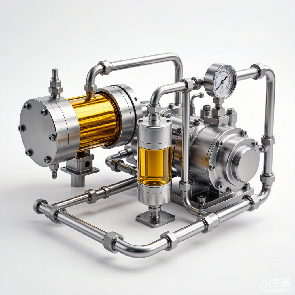
Figure: Compressor oil system rendering showing pump, cooler, filter, and separator components
Functions of Compressor Lubrication Oil
Lubrication oil in a compressor system serves far more purposes than merely reducing friction between moving parts. It is a multifunctional fluid that simultaneously provides sealing, cooling, lubrication, and noise attenuation. Understanding each of these functions is essential for selecting the right oil and maintaining the system properly.
- Sealing: In many compressor designs—particularly screw and reciprocating units—the oil forms a liquid seal between rotors, pistons, and cylinder walls. This seal minimizes internal gas leakage from the discharge side back to the suction, directly maintaining volumetric efficiency. Without adequate oil viscosity and distribution, internal blow-by increases dramatically, reducing capacity and raising discharge temperatures.
- Cooling: Compression generates substantial heat. The oil absorbs this heat from the rotors, bearings, and casing, then transfers it to the cooling medium via the oil cooler. In oil-flooded screw compressors, the oil injected directly into the compression chamber absorbs the heat of compression, enabling single-stage pressure ratios that would be impossible with dry compression. The oil’s specific heat capacity and flow rate determine the compressor’s thermal balance.
- Lubrication: The oil forms a hydrodynamic film between journal bearings and shafts, between rolling element bearings and raceways, and between timing gears in screw compressors. This film prevents metal-to-metal contact, reduces wear, and extends component life. The oil viscosity must be sufficient to maintain the film at operating temperature, yet not so high that it causes excessive power consumption or sluggish oil circulation.
- Noise reduction: The oil acts as a damping medium, absorbing the pressure pulsations and mechanical vibrations generated during compression. In oil-flooded screw compressors, the injected oil significantly attenuates the high-frequency noise produced by the rotor lobe pass. This damping effect contributes to meeting workplace noise regulations and reduces structural fatigue in piping and vessels.
Oil Selection Criteria
Selecting the correct lubricating oil is one of the most consequential decisions in compressor maintenance. The wrong oil can cause accelerated wear, deposit formation, varnishing, and even catastrophic failure. Selection criteria include viscosity grade, base stock type, additive package, and compatibility with the process gas or refrigerant.
Viscosity Grades (ISO VG 32, 46, 68)
The ISO viscosity grade (VG) system classifies oils by their kinematic viscosity at 40°C. For compressor lubrication, three grades predominate:
- ISO VG 32: The lightest commonly used grade, suitable for high-speed compressors with close bearing clearances, low ambient temperatures, and applications where energy efficiency is paramount. Typical applications include small rotary screw compressors and centrifugal compressor bearing oil systems operating in moderate climates.
- ISO VG 46: The most versatile grade, offering a balance between film strength and energy efficiency. It is the default choice for most medium-sized rotary screw and reciprocating compressors operating in temperate environments. VG 46 provides adequate viscosity at operating temperature while remaining fluid enough for cold-start circulation.
- ISO VG 68: A heavier grade used in large reciprocating compressors, high-temperature applications, and compressors with worn bearing clearances where a thicker film is needed. VG 68 provides superior film strength under high load but may cause higher power consumption and slower oil circulation in cold conditions.
The correct viscosity grade depends on the compressor type, operating speed, bearing clearances, ambient temperature range, and discharge temperature. Always consult the manufacturer’s lubrication specification before deviating from the recommended grade.
Synthetic vs. Mineral Oil Comparison
| Property | Mineral Oil | Synthetic Oil (PAO) | Synthetic Oil (Ester) |
|---|---|---|---|
| Oxidation stability | Moderate; degrades at high temperatures | Excellent; resists oxidation up to 130°C | Very good; stable in presence of moisture |
| Operating temperature range | -10°C to 100°C | -40°C to 130°C | -30°C to 120°C |
| Service life | 2,000–4,000 hours | 6,000–8,000 hours | 6,000–10,000 hours |
| Initial cost | Low (baseline) | 2–3x mineral oil cost | 3–5x mineral oil cost |
| Deposit formation | Prone to varnish and sludge at high temps | Minimal deposit formation | Low deposits; may hydrolyze with water |
| Compatibility | Good with most seals and paints | May shrink some elastomers; test seals | Excellent cleaning effect; may soften seals |
| Biodegradability | Poor | Moderate | Good to excellent |
| Best application | General-purpose, low-temp compressors | High-temperature rotary screw compressors | Refrigeration compressors with HFC refrigerants |
The lifecycle cost analysis often favors synthetic oils despite their higher initial cost. The extended drain intervals, reduced deposit formation, and lower energy consumption typically offset the price differential within the first year of operation. However, compatibility with existing seals, paints, and gaskets must be verified before switching from mineral to synthetic oil.
Compatibility with Refrigerants
In refrigeration compressors, the oil and refrigerant are in direct contact and must be chemically and physically compatible. The oil must not react with the refrigerant, and its viscosity must remain adequate when diluted by refrigerant at operating temperature. Traditional mineral oils work well with CFC and HCFC refrigerants (R-12, R-22) but are virtually immiscible with HFC refrigerants (R-134a, R-410A). For HFC systems, polyolester (POE) oils are the standard choice due to their excellent miscibility and chemical stability. Polyalkylene glycol (PAG) oils are used in some automotive air conditioning systems with R-134a. Always verify oil-refrigerant miscibility charts and follow the compressor manufacturer’s specification—using an incompatible oil can cause oil return failure, bearing starvation, and catastrophic compressor failure.
Oil System Components
A compressor oil system consists of several integrated components, each serving a specific function in the lubrication circuit. Understanding the role and maintenance requirements of each component is essential for troubleshooting oil system problems and preventing bearing failures.
Oil Pump
The oil pump circulates lubricating oil through the system at the required pressure and flow rate. Most compressor oil systems use a positive displacement gear pump—either external gear or internal gear type—driven by an electric motor or directly from the compressor shaft. Main pumps are typically shaft-driven to ensure lubrication whenever the compressor is running, while auxiliary pumps (AC motor-driven) provide pre-lubrication before startup and post-lubrication after shutdown. DC-backed emergency pumps ensure coast-down lubrication during power failures. Inspect pump internals for wear at major overhauls, and monitor pump discharge pressure and flow rate as part of routine condition monitoring.
Oil Cooler
The oil cooler removes the heat absorbed by the oil during compression and lubrication. Shell-and-tube heat exchangers are the most common design, with oil on the shell side and cooling water on the tube side. Air-cooled finned-tube coolers are used in applications where water is unavailable. The cooler must maintain the oil supply temperature within the manufacturer’s specified range—typically 40°C to 55°C at the bearing inlet. Fouling on either side of the cooler reduces heat transfer, causing rising oil temperatures. Monitor the oil temperature approach (the difference between oil outlet and cooling medium inlet temperatures) and clean the cooler when the approach exceeds the design value by more than 5°C.
Oil Filter
Oil filters remove particulate contaminants from the lubricant before it reaches the bearings and seals. Most systems use duplex filter arrangements with two filter housings connected in parallel, allowing filter element replacement without interrupting oil flow. The filter elements are typically depth-type with a nominal rating of 10 microns or better. Monitor the filter differential pressure gauge daily; change the element when the differential reaches the manufacturer’s recommended limit. Never allow the differential to reach the bypass valve cracking pressure, as this sends unfiltered oil to the bearings. When switching filter elements, always fill the standby housing with clean oil before placing it in service to prevent air entrainment.
Oil Separator
In oil-flooded screw and rotary vane compressors, the oil separator removes lubricating oil from the compressed gas stream before the gas is discharged to the process. The separator typically uses a two-stage design: a primary impingement or centrifugal stage that removes the bulk of the oil, followed by a coalescing filter element that captures fine oil mist. Separator efficiency directly affects oil consumption and downstream gas quality. A degraded coalescing element allows excessive oil carryover, depleting the reservoir and contaminating the process. Monitor the oil carryover rate and replace coalescing elements when the carryover exceeds the manufacturer specification or the element differential pressure reaches the change-out limit.
Pressure Regulating Valve
The pressure regulating valve maintains a constant oil supply pressure to the bearings and seals, regardless of variations in pump output or system demand. It typically diverts excess pump flow back to the reservoir. The valve is usually a spring-loaded piston or diaphragm type, adjustable via the spring preload. Verify the oil supply pressure periodically against the manufacturer’s setpoint, and inspect the valve internals for wear, spring fatigue, and seat damage during major overhauls. A malfunctioning pressure regulating valve can cause bearing oil starvation (if pressure is too low) or seal damage (if pressure is too high).
Common Oil System Failures
Oil system failures are a leading cause of compressor shutdowns. Recognizing the failure modes and their root causes enables proactive maintenance and prevents cascading damage to bearings, seals, and rotors.
Oil Degradation
Oxidation is the primary degradation mechanism for mineral oils. At elevated temperatures, oxygen reacts with hydrocarbon molecules to form peroxides, acids, and varnish-like deposits. The rate of oxidation approximately doubles for every 10°C rise in oil temperature above 80°C. Antioxidant additives slow this process but are consumed over time. Signs of oxidation include rising acid number (TAN), darkening oil color, and the appearance of insoluble deposits on bearing surfaces and filter elements. Synthetic oils (PAO, ester) have inherently better oxidation stability due to their uniform molecular structure.
Thermal breakdown occurs when oil is exposed to temperatures above its thermal stability limit. At temperatures exceeding 120°C for mineral oils or 150°C for synthetics, the hydrocarbon molecules thermally crack, producing light fractions (which lower the flash point) and heavy carbonaceous deposits (coke). Thermal breakdown is most common in reciprocating compressors with high discharge temperatures and in oil-flooded screw compressors with inadequate cooling. The resulting coke deposits block oil passages, cause valve sticking, and accelerate bearing wear.
Contamination includes water, process gas, particulate matter, and cross-contamination with incompatible oils. Water enters through condensation, cooler tube leaks, or seal leakage. Even 200 ppm of water can promote bearing corrosion and additive depletion. Process gas contamination dilutes the oil and may introduce corrosive compounds. Particulate contamination—from wear debris, rust, or airborne dirt—accelerates abrasive wear and blocks oil passages. Regular oil analysis is the primary defense against contamination-related failures.
Low Oil Pressure
Low oil pressure is one of the most common and immediately dangerous oil system faults. If uncorrected, it leads to bearing oil starvation and rapid failure. Causes and troubleshooting steps include:
- Clogged filter: Check the filter differential pressure. If it exceeds the change-out limit, switch to the standby filter and replace the element immediately.
- Oil pump wear: Measure pump discharge pressure at no-load and full-flow conditions. Compare to baseline values. Internal gear wear reduces pump capacity and requires pump rebuild or replacement.
- Oil leakage: Inspect external piping, flanges, and fittings for leaks. Check the bearing housing for internal leakage through the oil return passages.
- Low oil level: Verify the reservoir oil level against the sight glass marks. Low level may indicate oil carryover, leakage, or insufficient initial fill.
- Pressure regulating valve malfunction: Inspect the valve for stuck piston, weak spring, or debris on the seat. Clean or replace as needed and reset the pressure setpoint.
- Excessive bearing clearance: Worn bearings with increased clearance allow excessive oil flow through the bearing, reducing system pressure. Check bearing clearance and replace worn bearings.
Oil Carryover
Oil carryover refers to the loss of lubricating oil into the compressed gas discharge. In oil-flooded compressors, some carryover is normal, but excessive carryover depletes the oil reservoir, contaminates downstream equipment, and increases operating costs. Primary causes include degraded separator efficiency and oil foaming.
Separator efficiency degrades as the coalescing element becomes saturated, fouled, or physically damaged. Monitor the separator differential pressure—both high (fouled element) and low (bypassed or ruptured element) readings are abnormal. Replace the coalescing element at the recommended service interval or when differential pressure exceeds the change-out limit. Always use OEM-specified elements; aftermarket alternatives may have different coalescing efficiency and flow characteristics.
Foaming occurs when air is entrained in the oil and stabilized by contaminants, additives, or oil degradation products. Foamy oil has reduced effective density and is more easily carried by the gas stream. Causes include oil level above the maximum mark (allowing splashing by rotating components), air leaks in the pump suction line, and contamination with silicone or other surfactants. Address foaming by correcting the oil level, eliminating suction-side air leaks, and replacing the oil if anti-foam additives are depleted. Never add aftermarket anti-foam agents without consulting the oil manufacturer.
Oil Temperature Issues
Oil temperature too high accelerates oxidation, promotes coke formation, and reduces oil viscosity to the point that the bearing film cannot support the load. Causes include fouled oil coolers, insufficient cooling water flow, high ambient temperature, and excessive internal compressor heat generation from worn components. Coking—the formation of hard carbon deposits—is the most serious consequence of sustained high oil temperature. Coke deposits on valves, piston rings, and bearing oil galleries restrict flow, cause sticking, and accelerate wear. If oil temperature exceeds 80°C for mineral oil or 100°C for synthetic oil, investigate and correct the root cause immediately.
Oil temperature too low increases oil viscosity, impeding pumpability and slowing oil circulation through the system. At startup, cold oil may not reach the most distant bearings quickly enough, causing dry-start wear. High viscosity also increases pump power consumption and may cause the pressure regulating valve to chatter. In extreme cold, the oil may gel, blocking filter elements and causing a low-pressure trip. Install oil reservoir heaters with thermostatic control to maintain oil temperature above 20°C during cold starts. For compressors in unheated outdoor installations, consider using a lower viscosity grade oil or a synthetic oil with better low-temperature fluidity.
Oil Analysis and Condition Monitoring
Oil analysis is the single most valuable tool for monitoring compressor health. A well-structured oil analysis program can detect bearing wear, contamination, and oil degradation weeks or months before they cause a failure. The key is regular sampling, consistent test procedures, and disciplined trend analysis.
Regular Oil Sampling
- Particle count: Measures the concentration of solid particles by size range (e.g., 4, 6, 14, 21, 38, 70 microns) using automatic particle counters. Results are reported as ISO 4406 cleanliness codes. Typical targets for compressor oil are ISO 18/16/13 for gear-driven units and ISO 16/14/11 for clean bearing oil systems. Rising particle counts indicate filter bypass, internal wear, or contamination ingress.
- Water content: Measured by Karl Fisher titration and reported in parts per million (ppm). Water promotes corrosion, additive depletion, and bearing damage. For most compressor oils, water content should remain below 200 ppm. Levels above 500 ppm require immediate action—investigate the source (cooler leak, condensation, seal leakage) and purify or replace the oil.
- Spectrochemical analysis: Uses inductively coupled plasma (ICP) or rotary disk emission (RDE) spectroscopy to quantify wear metals (iron, copper, tin, lead, aluminum, chromium), contaminants (silicon, sodium, potassium), and additive elements (zinc, phosphorus, calcium, magnesium) in the oil. Each metal traces to specific components: iron to gears and shafts, copper and tin to bearing babbitt, silicon to dirt ingress, and sodium to cooler water leakage. Establish baseline concentrations for each element and set alarm thresholds based on trend deviations.
Trend Analysis and Alarm Limits
Individual oil analysis results are less informative than trends. A single iron reading of 15 ppm is meaningless without context; the same reading rising from 5 ppm to 15 ppm over three consecutive samples signals a problem. Establish trend baselines during the first 3 to 6 months of operation after an oil change, then set alarm limits using the two-sigma (warning) and three-sigma (critical) statistical thresholds. Review the trends monthly and correlate them with vibration data, performance parameters, and maintenance events. When multiple indicators converge—e.g., rising iron and copper combined with increasing vibration—schedule an inspection before the next planned outage.
Sampling frequency depends on the compressor type, criticality, and operating conditions. For critical centrifugal compressors, sample monthly. For general-purpose rotary screw compressors, sample quarterly. Increase the frequency after any major maintenance event, oil change, or abnormal operating episode. Always draw samples from the designated sampling valve while the compressor is running at normal operating conditions—samples from a shut-down machine or from the drain port do not represent the oil in circulation.
Best Practices for Oil Changes
Oil changes are the most fundamental yet frequently mishandled maintenance task. Proper procedure, correct intervals, and attention to flushing and storage details determine whether the fresh oil delivers its full service life or fails prematurely.
Change Intervals Based on Operating Hours
Oil change intervals depend on the oil type, compressor design, and operating severity. Typical guidelines are:
- Mineral oil in rotary screw compressors: Change every 2,000 to 4,000 operating hours, or annually, whichever comes first. Reduce the interval by 50% if discharge temperatures consistently exceed 100°C or if the compressor operates in a dirty environment.
- Synthetic oil (PAO) in rotary screw compressors: Change every 6,000 to 8,000 hours, or every two years. PAO oils maintain their viscosity and oxidation stability far longer than mineral oils.
- Centrifugal compressor bearing oil: Change every 8,000 to 12,000 hours, or as indicated by oil analysis. Large oil volumes and continuous filtration make condition-based changes more economical than fixed intervals.
- Reciprocating compressor oil: Change every 2,000 to 4,000 hours. Higher discharge temperatures and greater combustion blow-by accelerate degradation.
Regardless of the guideline, always use oil analysis as the final arbiter. If the acid number exceeds the condemn limit, if viscosity has changed by more than 10% from the original value, or if water content is above 500 ppm after purification attempts, change the oil immediately.
Flush Procedures
When changing oil, the old oil, varnish deposits, and contaminants must be removed from the system before introducing the fresh charge. A proper flush procedure includes the following steps:
- Drain the old oil: Drain the oil while the compressor is warm (just after shutdown) so that the oil flows freely and suspended particles are still dispersed. Drain from the reservoir, oil cooler, filter housings, and all low-point drains.
- Inspect the reservoir: Open the reservoir inspection cover and clean the interior manually. Remove all sludge and deposits with lint-free wipes. Inspect the reservoir coating for corrosion and blistering.
- Flush with flushing oil: Fill the reservoir with a dedicated flushing oil or the same grade as the charge oil. Run the auxiliary oil pump with the compressor uncoupled for 2 to 4 hours, circulating the oil through the system. Monitor the filter differential pressure and change elements as needed during the flush.
- Drain and recharge: Drain the flushing oil completely. Replace all filter elements with new units. Fill the reservoir with the correct charge oil to the specified level. Run the auxiliary pump for 15 minutes to bleed air, then verify oil pressure and temperature before starting the compressor.
When switching from mineral oil to synthetic oil, a more thorough flush is required to remove all mineral oil residue, as the two base stocks may be incompatible. Consult the oil supplier for specific flushing procedures and compatibility guidance.
Oil Storage and Handling
Improper storage and handling can introduce contamination that negates the benefits of a fresh oil change. Follow these practices to protect oil quality from the warehouse to the reservoir:
- Indoor storage: Store oil in a clean, dry, temperature-controlled environment. Outdoor storage exposes drums to temperature cycling that causes condensation and water accumulation inside the container.
- First-in, first-out (FIFO): Rotate stock to use the oldest oil first. Even sealed containers have shelf life limits—typically 3 years for mineral oil and 5 years for synthetic oil.
- Dedicated transfer equipment: Use dedicated, clearly labeled pumps, hoses, and containers for each oil type. Never use a container that previously held a different oil grade without thorough cleaning.
- Filter on transfer: Use a portable filtration cart with a 3-micron (or finer) filter when transferring oil from drums or totes into the compressor reservoir. This removes any contamination introduced during storage and handling.
- Seal opened containers: Reseal partially used drums and pails immediately. Open containers absorb moisture and collect dust, degrading the oil quality before it reaches the compressor.
Source: Compressor Maintenance Forum