
Compressor Performance Testing and Efficiency Evaluation
By Nick Li · August 10, 2026 · Technical Articles
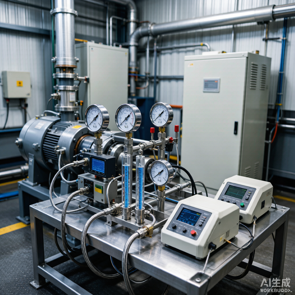
Performance testing is essential for verifying that compressors meet design specifications, identifying efficiency losses, and establishing baseline data for condition monitoring. This article presents the principles, methods, and standards for conducting comprehensive compressor performance evaluations.
1. Purpose of Performance Testing
Compressor performance testing serves multiple purposes throughout the equipment life cycle: acceptance testing after installation or overhaul, diagnostic testing for efficiency degradation, and benchmark testing for comparison with industry standards.
- Acceptance test: verify vendor performance guarantees after installation
- Diagnostic test: identify causes of efficiency loss or capacity shortfall
- Baseline test: establish reference data for future trend comparison
- Post-retrofit test: validate improvement after upgrade modifications
- Regulatory test: demonstrate compliance with energy or emission standards
2. Test Standards and Reference Codes
Several international standards govern compressor performance testing methodology, measurement requirements, and calculation procedures. Selecting the appropriate standard ensures test validity and comparability.
| Standard | Scope | Key Requirements |
|---|---|---|
| ASME PTC 10 | Centrifugal compressors | Full load or reduced load, corrected performance |
| ASME PTC 9 | Displacement compressors | Full load test at specified operating conditions |
| ISO 1217 | Displacement compressors (acceptance) | Simplified methods, practical tolerances |
| API 618 | Reciprocating compressors (design) | Necessary instrumentation and acceptance criteria |
| API 617 | Centrifugal compressors (design) | Test requirements for new equipment |
3. Measurement Parameters and Instrumentation
Accurate performance evaluation requires precise measurement of pressure, temperature, flow, speed, and power. The quality of instrumentation directly determines the reliability of test results.
3.1 Required Measurements
| Parameter | Instrument | Accuracy Class | Location |
|---|---|---|---|
| Suction pressure | Calibrated pressure transmitter | 0.1% FS | Suction nozzle, 2D-5D upstream |
| Discharge pressure | Calibrated pressure transmitter | 0.1% FS | Discharge nozzle, 2D-5D downstream |
| Suction temperature | RTD (4-wire) | Class A | Suction pipe, thermowell |
| Discharge temperature | RTD (4-wire) | Class A | Discharge pipe, thermowell |
| Flow rate | Orifice/Ultrasonic/Coriolis | 1.0% reading | Per ISO 5167 or equivalent |
| Speed | Magnetic pickup or encoder | 0.1% reading | Driver shaft |
| Power input | Power meter (2-wattmeter) | 0.5% reading | Motor terminals |
Figure 1: Compressor performance testing facility with instrumentation
4. Performance Calculation Methodology
The core performance metrics are calculated from measured data using thermodynamic principles. For reciprocating compressors, indicated work is derived from P-V diagrams; for centrifugal compressors, polytropic head and efficiency are computed.
4.1 Reciprocating Compressor Calculations
- Volumetric efficiency: actual flow / theoretical displacement (piston area x stroke x speed)
- Isentropic efficiency: isentropic work / indicated work from P-V diagram
- Mechanical efficiency: indicated power / shaft power input
- Specific energy: kW / (m3/min free air) for comparison benchmarking
- Capacity correction: adjust to reference suction conditions per ASME PTC 9
4.2 Centrifugal Compressor Calculations
- Polytropic head: H_p = ZRT * n/(n-1) * [(P2/P1)^((n-1)/n) – 1]
- Polytropic efficiency: eta_p = (n/(n-1)) / (k/(k-1)) * eta_q
- Power: Gas power = mass_flow * H_p / 3600 (kW)
- Surge margin: (Q_operating – Q_surge) / Q_surge x 100%
- Stonewall margin: (Q_stonewall – Q_operating) / Q_stonewall x 100%
5. Test Tolerances and Acceptance Criteria
Performance test results must be evaluated against defined tolerances to determine whether the compressor meets its contractual or design requirements. These tolerances account for measurement uncertainty and normal operational variability.
| Parameter | Tolerance | Reference Standard |
|---|---|---|
| Capacity | ±3% of guaranteed value | ASME PTC 9 / API 618 |
| Power consumption | +3% of guaranteed value | ASME PTC 10 / API 617 |
| Efficiency | -2% of guaranteed value | Vendor specification |
| Discharge temperature | +5 C of predicted value | API 618 |
| Speed | ±1% of rated speed | Test procedure |
6. Efficiency Loss Diagnosis
When performance test results indicate efficiency below expectations, a systematic diagnostic process is needed to identify and quantify the contributing loss mechanisms.
| Loss Source | Diagnostic Method | Typical Impact |
|---|---|---|
| Valve leakage | P-V diagram analysis | 3-15% capacity loss |
| Piston ring wear | Blowby measurement + P-V | 2-8% efficiency loss |
| Packing leakage | Leakage rate measurement | 1-3% capacity loss |
| Clearance volume excess | Volumetric efficiency calculation | 5-10% capacity loss |
| Cylinder wall scoring | Bore inspection | Progressive degradation |
7. Reporting and Documentation
A complete performance test report documents all measured data, calculations, instrument calibrations, and comparison with guarantee values. This report serves as a permanent record and baseline for future reference.
- Record all instrument calibration certificates and traceability
- Document test conditions: ambient, gas composition, suction state
- Present corrected performance results at specified reference conditions
- Include uncertainty analysis for all calculated parameters
- Provide trend comparison with previous test results if available
Source: Compressor Technology Editorial Reference