
Compressor Seal Selection: Mechanical Seals vs. Lip Seals
By Nick Li · August 10, 2026 · Technical Articles
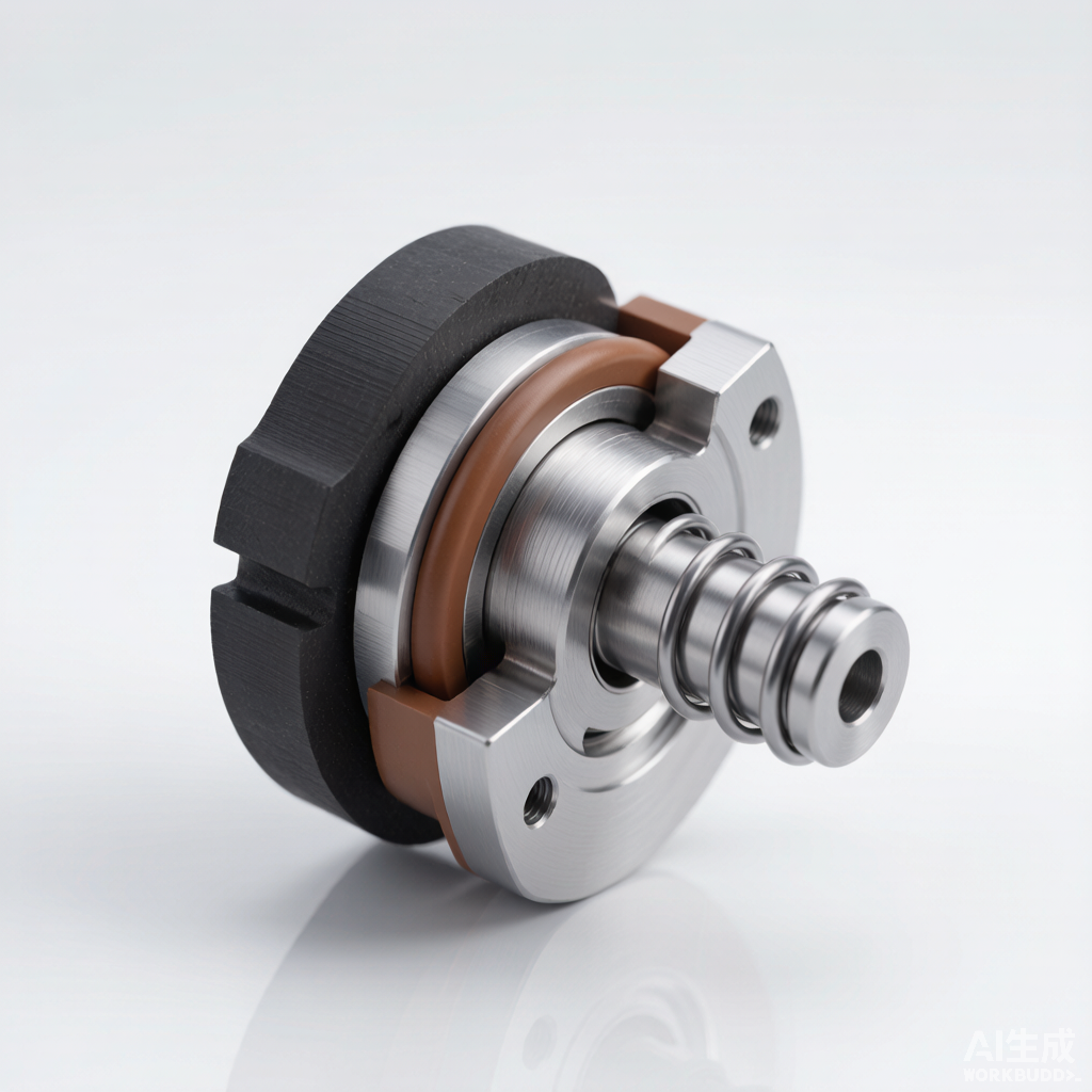
Figure: Cross-sectional view of a mechanical seal used in industrial compressors, showing the rotating face, stationary face, and secondary sealing elements.
Introduction to Compressor Sealing
Sealing systems are among the most critical components in compressor design and operation. Their primary function is to contain the process gas within the compressor casing, prevent leakage to the atmosphere, and isolate the lubricant from the process medium. The effectiveness of the sealing system directly influences compressor efficiency, emissions compliance, and overall equipment reliability. In industrial settings—ranging from petrochemical plants to natural gas transmission stations—seal failures rank among the leading causes of unplanned compressor shutdowns, making seal selection a decision of considerable engineering importance.
Purpose of Compressor Seals
- Contain process gas: The seal must hold the compressed gas within the casing under all operating conditions, including pressure transients and start-stop cycles, to maintain compressor efficiency and meet environmental regulations.
- Prevent leakage: Minimizing fugitive emissions is essential for both safety and regulatory compliance. Even small leaks of hazardous or flammable gases can pose significant risks to personnel and the surrounding environment.
- Isolate lubricant: Seals prevent process gas from mixing with bearing lubricant and vice versa, protecting both the lubrication system and the gas stream from contamination.
Operating Conditions
The selection of an appropriate seal type depends heavily on the operating envelope of the compressor. Engineers must evaluate several interrelated parameters:
- Pressure: Sealed gas pressure can range from near-atmospheric in blower applications to over 1,000 bar in high-pressure gas injection compressors. The pressure differential across the seal dictates the required mechanical design and face loading.
- Temperature: Process gas temperatures may vary from cryogenic conditions (below -150 °C) to high-temperature applications exceeding 300 °C. Seal materials must retain their mechanical properties across the full temperature range.
- Speed: Shaft rotational speeds in centrifugal compressors can exceed 30,000 rpm. High surface speeds generate frictional heat at the seal interface, requiring materials and designs capable of dissipating that heat without degradation.
- Medium: The chemical composition of the sealed gas—including corrosive components such as hydrogen sulfide, carbon dioxide, or chlorides—affects material compatibility. Additionally, the presence of liquid droplets or particulate matter can erode seal faces.
Mechanical Seals
Mechanical seals are precision-engineered devices that provide a dynamic seal between a rotating shaft and a stationary housing. They are the predominant seal type in modern industrial compressors, particularly in demanding applications where leakage tolerance is minimal and reliability expectations are high. Unlike gland packing or lip seals, mechanical seals rely on controlled contact between two flat, lapped faces—one rotating with the shaft and one stationary—to create a barrier against fluid migration.
Design Components
A mechanical seal comprises several precision components, each serving a specific function in the sealing mechanism:
- Rotating face: This primary sealing element is affixed to the shaft and rotates with it. It is typically manufactured from hard materials such as silicon carbide or tungsten carbide, which provide excellent wear resistance and thermal conductivity.
- Stationary face: Mounted in the seal housing, this face remains stationary and mates against the rotating face. It is commonly made from softer carbon-graphite materials, creating a sacrificial wear surface that conforms to the harder rotating face.
- Secondary seals: O-rings, gaskets, or bellows positioned behind the primary faces prevent leakage along the shaft and housing. These elastomeric or metallic components must be chemically compatible with the process medium.
- Springs: A spring mechanism—either a single coil spring, multiple small springs, or a metal bellows—maintains face contact during shaft movement, pressure fluctuations, and at standby. The spring load ensures the faces remain in contact even when hydraulic pressure is absent.
Balanced vs. Unbalanced Seals
The balance ratio of a mechanical seal describes the proportion of the sealed pressure that acts to close the seal faces. An unbalanced seal has a balance ratio greater than 1.0, meaning the full hydraulic force presses the faces together. While simpler in design and lower in cost, unbalanced seals generate higher face loading, which can lead to excessive heat generation and accelerated wear at elevated pressures.
Balanced seals incorporate a stepped shaft sleeve or seal geometry that reduces the hydraulic closing force, achieving a balance ratio typically between 0.65 and 0.85. This reduction in face loading lowers frictional heat, extends face life, and enables operation at significantly higher pressures—often exceeding 100 bar. The trade-off is a more complex geometry and somewhat higher manufacturing cost. For most industrial compressor applications operating above 15 bar, balanced seals are the standard choice.
Single, Double, and Tandem Arrangements
Mechanical seals can be configured in several arrangements depending on the leakage tolerance, safety requirements, and process gas characteristics:
- Single seals: One set of sealing faces handles the full pressure differential. They are the simplest and most economical configuration, suitable for non-hazardous, non-toxic gases where minor leakage to atmosphere is acceptable.
- Double seals: Two seals are arranged back-to-back or face-to-face with a barrier fluid circulated between them at a pressure higher than the process gas. This configuration provides zero process leakage to atmosphere, as any seal failure results in barrier fluid migration rather than gas escape. Double seals are mandatory for toxic, hazardous, or environmentally regulated gases.
- Tandem seals: Two seals are arranged in series, with the primary seal handling the full pressure and the secondary seal acting as a backup. The inter-seal cavity is typically vented to a flare or recovery system. If the primary seal fails, the secondary seal takes over, preventing uncontrolled release. Tandem arrangements are widely used in natural gas and petrochemical applications.
Dry Gas Seals for Centrifugal Compressors
Dry gas seals (DGS) represent a specialized category of mechanical seals developed specifically for centrifugal compressors in the oil and gas industry. Unlike traditional liquid-lubricated seals, DGS operate without any liquid lubricant between the faces. Instead, the rotating face features shallow spiral-groove patterns etched into its surface. As the shaft rotates, these grooves pump gas inward, creating a pressurized film that separates the faces by a gap of approximately 2 to 5 micrometers. This non-contacting design eliminates face wear during normal operation, resulting in extraordinarily long seal life.
Dry gas seals can handle pressures up to 450 bar and surface speeds exceeding 150 m/s, making them suitable for the most demanding centrifugal compressor services. They require a clean, dry supply of buffer or seal gas—typically filtered nitrogen or a side-stream of the process gas—to prevent contamination of the groove pattern. DGS systems include sophisticated filtration, monitoring, and control panels to ensure gas quality and detect seal degradation. While the capital cost is high, the elimination of seal oil systems, reduced maintenance, and near-zero process leakage make dry gas seals the preferred choice for large centrifugal compressors in gas transmission and processing facilities.
Advantages of Mechanical Seals
- Low leakage: Properly designed and maintained mechanical seals achieve emission rates below 500 ppm, and dry gas seals can approach zero measurable leakage.
- Long service life: Mechanical seals typically last 3 to 5 years in standard service, and dry gas seals can exceed 5 to 8 years, significantly reducing maintenance frequency.
- High pressure and temperature capability: Balanced and DGS designs handle pressures from vacuum to 450+ bar and temperatures from cryogenic to over 300 °C, far exceeding the limits of lip or labyrinth seals.
- Reduced friction and power loss: The controlled face contact in balanced seals, and the non-contacting film in DGS, result in lower frictional power consumption compared to packing or lip seals.
Disadvantages of Mechanical Seals
- Higher cost: A complete mechanical seal assembly can cost 5 to 20 times more than an equivalent lip seal, and dry gas seal systems with associated controls can represent a major capital investment.
- Sensitivity to misalignment: Shaft misalignment, runout, or vibration beyond the seal’s design tolerances can cause face damage and premature failure. Precise installation and shaft condition are critical.
- Vulnerability to contamination: Particulates or liquid droplets in the process gas can damage the lapped faces or clog dry gas seal grooves, requiring thorough filtration of buffer gas supplies.
- Complex repair: Seal replacement typically requires compressor disassembly, and rebuild should only be performed by qualified personnel or returned to the manufacturer.
Lip Seals (Radial Shaft Seals)
Lip seals, also known as radial shaft seals or oil seals, are among the simplest and most widely used sealing devices in rotating equipment. In compressor applications, they are predominantly found in smaller, lower-pressure units such as refrigeration compressors, air compressors, and utility blowers. Their popularity stems from low cost, compact dimensions, and ease of installation. However, their operating envelope is significantly narrower than that of mechanical seals, limiting their use to less demanding services.
Design and Construction
A lip seal consists of three principal elements that work together to create a dynamic seal against the rotating shaft:
- Elastomer lip: The sealing element is a flexible elastomeric lip that contacts the shaft surface. The lip geometry includes a beam section, heel, and contact edge. A hydrodynamic pumping pattern molded into the lip returns leaked fluid back toward the sealed side, enhancing sealing effectiveness.
- Metal case: A stamped metal outer case provides structural rigidity and enables press-fit installation into the housing bore. The case also protects the elastomer during handling and operation. Some designs incorporate a rubber outer coating to improve bore sealing.
- Garter spring: A coiled garter spring fitted into a groove on the lip’s heel maintains a controlled radial load on the shaft surface. This spring compensates for lip relaxation over time and ensures consistent contact pressure throughout the seal’s service life.
Common Materials
The elastomer compound selected for the lip must match the process conditions, particularly temperature and chemical compatibility:
- NBR (Nitrile Butadiene Rubber): The most economical and widely used material, NBR offers good resistance to mineral oils and fuels. Its operating temperature range of -40 °C to +120 °C covers many general-purpose compressor applications.
- FKM (Fluorocarbon/Viton): FKM provides superior high-temperature performance up to 200 °C and excellent chemical resistance to a broad range of oils, fuels, and solvents. It is the preferred material for more demanding services where NBR would degrade prematurely.
- PTFE (Polytetrafluoroethylene): PTFE lips offer exceptional chemical inertness, very low friction, and temperature capability from -70 °C to +250 °C. PTFE seals can also handle higher surface speeds and moderate pressures better than standard elastomer lips. However, PTFE lacks the elasticity of rubber and may not conform as well to shaft irregularities.
Advantages of Lip Seals
- Low cost: Lip seals are inexpensive to manufacture and purchase, typically costing a fraction of a mechanical seal, making them ideal for cost-sensitive or high-volume applications.
- Simple installation: Lip seals are installed by press-fitting into a standard housing bore without special tooling or complex alignment procedures, reducing installation time and labor.
- Compact size: The minimal axial and radial space requirement of lip seals allows their use in compact compressor designs where space constraints preclude mechanical seals.
- No auxiliary systems: Unlike double mechanical seals or dry gas seals, lip seals require no barrier fluid, buffer gas, or filtration systems, simplifying the overall compressor package.
Disadvantages of Lip Seals
- Limited pressure rating: Standard lip seals are typically rated for pressure differentials below 5 bar, with specialized reinforced designs reaching perhaps 10 bar. Beyond these limits, the lip lifts off the shaft, causing immediate failure.
- Higher leakage: Lip seals inherently leak more than mechanical seals due to the dynamic lip-shaft interface. They are unsuitable for applications with strict emissions requirements.
- Shorter service life: The elastomer lip wears continuously against the shaft, typically lasting 1,000 to 5,000 hours. Hardening, cracking, and loss of resilience over time necessitate frequent replacement.
- Shaft wear: The radial load from the garter spring can create a wear groove on the shaft surface over time, eventually requiring shaft sleeve replacement.
Labyrinth Seals
Labyrinth seals are non-contacting seals that restrict fluid flow through a tortuous path of alternating fins and chambers. Rather than forming a positive barrier, they create maximum flow resistance to minimize leakage. In compressor applications, labyrinth seals are commonly used as interstage seals between impeller stages, shaft end seals in lower-pressure services, and as part of a dry gas seal system to isolate the seal from process gas.
Design Principle
The labyrinth seal consists of a series of sharp-edged fins—either on the rotating shaft or the stationary housing—that project into annular chambers. As gas passes each fin, it undergoes a throttling expansion that converts pressure energy into kinetic energy, which is then dissipated as turbulence in the chamber. This process repeats at each stage, progressively reducing the driving pressure and limiting mass flow. The clearance between the fin tip and the mating surface is typically 0.1 to 0.3 mm, small enough to restrict flow but large enough to avoid contact during transient shaft movements.
Advantages of Labyrinth Seals
- Non-contact operation: Since there is no physical contact between rotating and stationary parts, labyrinth seals generate no friction, produce no wear debris, and require no lubrication.
- High speed capability: The absence of contact means labyrinth seals can operate at the highest shaft speeds encountered in compressor service without speed-related limitations.
- No wear: With no rubbing contact, labyrinth seals have effectively unlimited mechanical life, barring damage from foreign objects or rotor rubs during severe transients.
- Temperature tolerant: Constructed entirely from metal (typically aluminum, steel, or exotic alloys), labyrinth seals tolerate extreme temperatures that would destroy elastomeric seals.
Disadvantages of Labyrinth Seals
- Higher leakage: Labyrinth seals are inherently leaky by design. They reduce—not eliminate—flow, making them unsuitable as the sole seal for hazardous or valuable gases.
- Limited pressure differential: Each labyrinth stage can accommodate a limited pressure drop. High differentials require many stages, increasing axial length. Typical practical limits are 10 to 50 bar depending on the number of stages and clearance.
- Clearance sensitivity: If the operating clearance increases—due to thermal growth, centrifugal growth, or damage—leakage rises dramatically. Manufacturing tolerances and rotor dynamics must be carefully controlled.
Selection Criteria
The following comparison table summarizes the key performance attributes of the three seal types discussed. Engineers should use this as a starting point for seal selection, with final decisions based on manufacturer data, application-specific requirements, and operating experience.
| Criterion | Mechanical Seals | Lip Seals | Labyrinth Seals |
|---|---|---|---|
| Pressure Rating | Up to 450 bar (DGS) | Up to 5–10 bar | Up to 10–50 bar |
| Temperature Range | -150 °C to +300 °C | -40 °C to +200 °C | -200 °C to +500 °C |
| Speed Limit | Up to 150 m/s (DGS) | Up to 30–40 m/s | No practical limit |
| Leakage Rate | Very low (< 500 ppm) | Moderate | High (inherent by design) |
| Service Life | 3–8 years | 1,000–5,000 hours | Unlimited (no wear) |
| Relative Cost | High | Low | Moderate |
| Maintenance | Periodic inspection; complex rebuild | Frequent replacement; simple | Minimal (inspect clearances) |
| Friction / Power Loss | Low (balanced) to negligible (DGS) | Moderate | Negligible (non-contact) |
| Typical Application | Centrifugal compressors, high-P/T service | Small air/refrigeration compressors | Interstage seals, low-pressure shaft ends |
Installation and Maintenance
Even the most carefully selected seal will underperform or fail prematurely if installation and maintenance practices are inadequate. Proper procedures, trained personnel, and disciplined execution are essential to realizing the design life of any compressor seal.
Shaft Surface Preparation
The shaft (or shaft sleeve) surface beneath a dynamic seal is a precision component that directly affects seal performance and longevity. For mechanical seals, the surface finish at the secondary seal contact area should be 0.4 to 0.8 µm Ra, while the face running area must be within 0.2 µm Ra and free of scratches, corrosion, or coating defects. For lip seals, the shaft surface should be 0.2 to 0.5 µm Ra, with a hardness of at least 55 HRC to resist wear from the garter spring load.
Key preparation requirements include ensuring concentricity of the shaft to the housing bore (typically within 0.05 mm TIR), removing all burrs and sharp edges at installation grooves, and thoroughly cleaning the shaft with a lint-free solvent wipe immediately before seal installation. Any nicks or scratches on the running surface must be polished out, as even microscopic defects can create leakage paths under a mechanical seal face or accelerate lip wear.
Common Failure Modes
Understanding the predominant failure modes enables effective troubleshooting and preventive action:
- Face wear and heat checking: In mechanical seals, inadequate lubrication or excessive face loading causes thermal distress, visible as radial cracks (heat checks) on the face. Root causes include loss of barrier fluid, blocked cooling passages, or pressure transients beyond seal rating.
- Elastomer degradation: Lip seals and mechanical seal secondary seals suffer from hardening, cracking, or swelling due to chemical incompatibility, excessive temperature, or age. Compression set in O-rings reduces sealing force over time.
- Erosion and groove clogging: In dry gas seals, contaminated buffer gas introduces particulates that erode the silicon carbide faces or obstruct the spiral grooves, causing face contact and rapid failure. Filtration system integrity is paramount.
- Shaft fretting and wear groove: Lip seal garter springs gradually wear a circumferential groove into the shaft surface. Once the groove depth exceeds approximately 0.25 mm, the lip cannot maintain contact, and the shaft or sleeve must be replaced or reconditioned.
- Spring fatigue: Mechanical seal springs and lip seal garter springs can lose tension over extended service, particularly at elevated temperatures, reducing closing force and increasing leakage.
Storage and Handling
Seals are precision components and must be stored and handled accordingly. The following guidelines preserve seal integrity between receipt and installation:
- Environmental control: Store seals in a clean, dry environment at temperatures between 10 °C and 25 °C, away from direct sunlight, ozone sources, and ultraviolet light that degrade elastomers.
- Original packaging: Keep seals in their original protective packaging until immediately before installation. The packaging protects lapped faces from damage and elastomers from environmental exposure.
- Shelf life management: Elastomeric components have finite shelf lives—typically 5 to 7 years for FKM and 3 to 5 years for NBR. Implement a first-in, first-out (FIFO) inventory system and discard seals that exceed manufacturer-recommended shelf life.
- Handling precautions: Never place mechanical seal faces on hard surfaces or touch lapped faces with bare fingers, as skin oils and microscopic debris can compromise flatness. Use clean, lint-free gloves and dedicated handling tools.
- Pre-installation inspection: Visually inspect all seal components for shipping damage. Verify dimensions against drawing requirements and confirm that elastomer durometer and material certification match the specified compound.
Source: Compressor Maintenance Forum