
Condition Monitoring and Predictive Maintenance for Compressors
By Nick Li · August 10, 2026 · Technical Articles
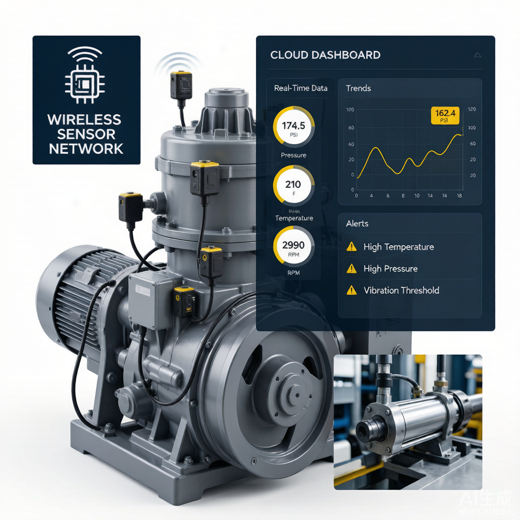
Figure: Compressor condition monitoring dashboard displaying real-time vibration, temperature, and performance data for predictive maintenance analytics.
Evolution of Maintenance Strategies
The philosophy governing industrial equipment maintenance has undergone a profound transformation over the past several decades. What began as a purely reactive endeavor—fixing equipment only after it failed—has evolved through successive stages of sophistication into today’s data-driven predictive and prescriptive approaches. Understanding this progression is essential for compressor operators seeking to optimize their maintenance programs and justify the investment in condition monitoring technologies.
From Reactive to Prescriptive: Four Generations
- Reactive maintenance (run-to-failure): The earliest and simplest strategy, in which equipment operates until it breaks, at which point repairs are initiated. While appropriate for non-critical, easily replaceable components, reactive maintenance applied to compressors results in catastrophic failures, extended downtime, collateral damage, and unpredictable production losses. Total cost of ownership is typically the highest under this approach.
- Preventive maintenance (time-based): Also called scheduled maintenance, this strategy performs maintenance at fixed time or operating-hour intervals regardless of actual equipment condition. It reduces unplanned failures compared to reactive approaches but suffers from two fundamental weaknesses: unnecessary maintenance is performed on healthy equipment, and some failures still occur between scheduled intervals. Studies indicate that up to 70% of scheduled maintenance tasks provide no measurable benefit.
- Predictive maintenance (condition-based): Predictive maintenance leverages real-time and near-real-time condition data to trigger maintenance only when the equipment shows signs of degradation. By monitoring parameters such as vibration, temperature, oil quality, and performance, maintenance teams can detect incipient faults weeks or months before functional failure, enabling planned intervention during scheduled outages. The U.S. Department of Energy reports that predictive maintenance programs typically deliver a 25% to 30% reduction in maintenance costs, a 70% to 75% reduction in breakdowns, and a 35% to 45% reduction in downtime.
- Prescriptive maintenance (AI-driven): The latest evolutionary step augments predictive maintenance with artificial intelligence and machine learning to not only detect anomalies but also recommend specific corrective actions. Prescriptive systems analyze historical outcomes, simulate intervention scenarios, and prescribe the optimal maintenance action, timing, and resource allocation to minimize total cost and risk.
Benefits of Predictive Maintenance
For compressor operators, the transition to predictive maintenance yields measurable and sustained benefits across multiple dimensions of plant performance. Industry benchmarks consistently demonstrate the following improvements:
- Maintenance cost reduction: By eliminating unnecessary scheduled maintenance and catching problems early—before they cause secondary damage—facilities typically achieve a 25% to 30% reduction in direct maintenance expenditures.
- Downtime reduction: Unplanned outages decrease by 35% to 50%, as maintenance is performed during planned windows rather than in response to failures. This directly improves compressor availability and production throughput.
- Asset life extension: Early detection and correction of degrading conditions—such as bearing wear, seal leakage, or fouling—prevents accelerated deterioration, extending compressor useful life by an estimated 20% to 40%.
- Energy efficiency: Monitoring performance degradation enables timely cleaning, re-wheeling, or reconfiguration to restore efficiency. Compressors operating under predictive maintenance programs consume 5% to 15% less energy than those maintained reactively.
- Safety and environmental compliance: Early fault detection reduces the risk of catastrophic failures that can release hazardous gases or cause injuries, supporting compliance with OSHA, EPA, and industry standards.
Vibration Monitoring
Vibration analysis is the cornerstone of compressor condition monitoring. Because every mechanical component generates characteristic vibration signatures during operation, deviations from baseline patterns provide early and specific indications of developing faults. In compressor applications, vibration monitoring detects bearing degradation, rotor unbalance, misalignment, looseness, resonance, aerodynamic instabilities such as surge and stall, and gear defects in integral gear-driven units. A well-designed vibration monitoring program can identify most mechanical faults weeks to months before functional failure occurs.
Continuous Online Monitoring vs. Periodic Route-Based
Two fundamental approaches to vibration data collection exist, each suited to different equipment criticality and risk profiles:
- Continuous online monitoring: Permanently installed proximity probes (for sleeve bearings) or accelerometers (for rolling element bearings) acquire vibration data continuously, with automated analysis and alerting. This approach is standard for critical centrifugal compressors in refining, petrochemical, and gas transmission services, where the cost of an unplanned outage justifies the capital investment in a machinery protection system (typically complying with API 670). Continuous systems provide immediate detection of rapid-onset faults and support advanced diagnostic techniques such as orbit analysis, full-spectrum analysis, and transient data capture during startups and shutdowns.
- Periodic route-based monitoring: Trained technicians use portable data collectors to acquire vibration readings at pre-defined points on a scheduled route—typically monthly or quarterly. This approach is cost-effective for less critical compressors and ancillary equipment where continuous monitoring is not warranted. Route-based programs can detect slowly developing faults but may miss rapid degradation between data collection intervals.
Many facilities employ a hybrid strategy: continuous monitoring on critical compressors with route-based surveillance on supporting equipment, creating a tiered approach that balances cost and coverage.
Wireless Vibration Sensors
Recent advances in wireless sensor technology have dramatically expanded the accessibility and scalability of vibration monitoring. Battery-powered wireless accelerometers can be mounted on virtually any compressor or driven equipment without the cabling, conduit, and installation costs associated with traditional wired systems. Modern wireless sensors transmit data via protocols such as Wi-Fi, Bluetooth, LoRaWAN, or ISA100 Wireless to central gateways, with battery life extending 3 to 7 years depending on transmission frequency.
Wireless sensors enable monitoring of previously unmonitored equipment—such as small reciprocating compressors, motor-driven auxiliary units, and remote pipeline compressor stations—where wired infrastructure was cost-prohibitive. They also facilitate temporary monitoring during commissioning, troubleshooting, or post-repair verification. The trade-offs include lower data resolution and transmission frequency compared to wired systems, making them better suited for general surveillance than high-speed machinery protection.
Automated Alert Thresholds
Effective vibration monitoring requires well-defined alert thresholds that balance sensitivity to real faults against the risk of false alarms. Industry standards such as ISO 10816 and ISO 20816 provide baseline severity charts for different machine types and mounting configurations, but optimal thresholds should be refined based on each compressor’s baseline characteristics and operating history. A typical alert structure includes:
- Alert threshold: Set at approximately 2 to 2.5 times the baseline vibration level, this threshold indicates a change that warrants investigation. Maintenance personnel receive a notification to review the data and plan further analysis, but operations continue normally.
- Danger threshold: Set at approximately 3.5 to 4 times baseline (or per ISO severity zone D), this threshold indicates a serious condition that may require immediate action. Critical compressors typically trigger automatic machinery shutdown at this level to prevent catastrophic failure.
- Rate-of-change alerts: In addition to absolute thresholds, monitoring systems track the rate of vibration increase. A rapid upward trend—even below the alert threshold—can signal an accelerating fault and should trigger expedited investigation.
Thermographic Inspection
Infrared (IR) thermography is a non-contact diagnostic technique that visualizes surface temperature distributions using infrared imaging cameras. By detecting abnormal heat patterns, thermography identifies electrical, mechanical, and process-related problems in compressors and their support systems before they escalate to failure. The technique is particularly valuable because thermal anomalies often precede mechanical or electrical failure by weeks or months, providing a wide window for planned intervention.
IR Imaging Applications
Thermographic inspections in compressor installations target several key areas:
- Electrical connections: Loose, corroded, or degraded electrical connections in motor terminals, switchgear, circuit breakers, and control panels generate excess heat due to increased resistance. IR imaging detects hot spots that are invisible during normal visual inspection, preventing arc flashes, motor failures, and electrical fires. Motor winding overheating—indicating overload, voltage imbalance, or impending bearing failure—is also visible.
- Bearings: Elevated bearing housing temperatures signal lubrication degradation, overload, or internal bearing damage. Thermography can identify temperature differentials between bearings on the same shaft, pinpointing the affected bearing before vibration levels rise to alert thresholds.
- Heat exchangers: IR imaging of intercoolers, aftercoolers, and oil coolers reveals flow blockages, fouling, and tube plugging that reduce heat transfer efficiency. Blocked passages appear as cold spots on the surface, while fouled areas show reduced temperature differential between inlet and outlet.
Temperature Trend Analysis
Single-point thermographic surveys provide snapshots of equipment condition, but their analytical power multiplies when temperature data is tracked over time. Trend analysis involves recording baseline thermal profiles of critical components and conducting periodic re-surveys—typically quarterly—to detect gradual changes. Software tools can overlay successive IR images and automatically highlight regions where temperature has increased beyond a defined threshold, directing attention to developing problems.
For compressor installations, trend analysis is particularly effective for monitoring gradual fouling of heat exchangers (indicated by progressive temperature rise), slow deterioration of motor bearings (increasing bearing temperature at constant load), and loosening of electrical connections (increasing connection temperature). Establishing trend baselines under known operating conditions—load, ambient temperature, and cooling medium flow—enables meaningful comparisons and eliminates false positives from normal operational variability.
Oil Analysis Program
Lubricant analysis is one of the most information-rich condition monitoring techniques available for compressors. The lubricant circulating through bearings, gears, and seals acts as a carrier medium, collecting wear particles, contaminants, and degradation byproducts that reflect the health of internal components. Regular oil analysis can detect bearing wear, gear tooth deterioration, seal degradation, lubricant breakdown, and contamination ingress—often before any other monitoring technology registers an anomaly.
Wear Metal Analysis
Spectrometric analysis of the lubricant identifies and quantifies metallic wear particles suspended in the oil. Each metal originates from specific compressor components, enabling targeted diagnosis of the wear source:
- Iron (Fe): The most common wear metal, originating from journal bearings, rolling element bearings, shaft surfaces, and gear teeth. Rising iron levels indicate general mechanical wear, often linked to lubricant degradation, contamination, or overload.
- Copper (Cu): Primarily from copper-lead or bronze bearing overlays, bushings, and retainers. Elevated copper often signals bearing overlay wear, particularly in turbomachinery sleeve bearings.
- Chromium (Cr): Originates from hardened steel components such as rolling element bearing races and balls, piston rings, and shaft surfaces. Chromium presence typically indicates more severe, abrasive wear of hardened surfaces.
- Tin (Sn): Found in babbitt bearing overlays (tin-based babbitting is common in large compressor journal bearings). Rising tin levels, often alongside copper, indicate bearing overlay deterioration.
- Aluminum (Al): Originates from aluminum bearing cages, pistons (in reciprocating compressors), and housing components. In centrifugal compressors, aluminum typically appears when aluminum-based bearing components are wearing.
- Lead (Pb): From lead-based bearing overlays and occasional gear components. Lead is less common in modern compressors due to environmental regulations, but may appear in older equipment.
Contaminant Monitoring
Contaminants in the lubricant are frequently the root cause of accelerated wear and must be monitored alongside wear metals:
- Water: Water contamination—whether from cooler leaks, seal leakage, condensation, or washdown—is highly detrimental to compressor lubrication. Even trace amounts (above 200 ppm in turbines) promote rust, accelerate oil oxidation, degrade bearing overlays, and reduce lubricant film strength. Karl Fischer titration provides accurate water quantification down to ppm levels.
- Particulate: Solid particles from atmospheric dust, wear debris, or combustion products act as abrasives that generate additional wear in a self-accelerating cycle. ISO Cleanliness Codes (e.g., ISO 4406) quantify particulate contamination by particle size ranges, with target levels specified by compressor manufacturers based on bearing type and speed.
- Glycol: In compressors with glycol-cooled heat exchangers, cooler tube leaks can introduce glycol into the lubricant. Glycol reacts with oil additives to form sludge and varnish, causing valve sticking, filter plugging, and accelerated wear. Chemical tests can detect glycol at concentrations as low as 50 ppm.
Oil Degradation
The lubricant itself degrades over time through oxidation, thermal stress, and additive depletion. Monitoring oil condition parameters ensures the lubricant remains fit for service:
- Viscosity: The single most important lubricant property. Viscosity outside the specified grade (typically ±10% of the ISO VG nominal value) indicates contamination with a different fluid, severe shear thinning, or polymer breakdown. Low viscosity reduces film thickness and risks bearing wear; high viscosity increases power consumption and can cause lubricant starvation at startup.
- Total Acid Number (TAN): TAN measures the concentration of acidic oxidation products in the oil. A rising TAN trend indicates progressive oxidation; when TAN exceeds the manufacturer’s condemning limit (often a 2.0 mg KOH/g increase over new oil), the oil should be changed to prevent corrosive wear.
- Oxidation: Fourier Transform Infrared (FTIR) spectroscopy directly measures oxidation byproducts, nitration, and sulfation in the lubricant. FTIR provides early warning of oil degradation before TAN or viscosity shift measurably, enabling proactive oil changes.
Sampling Frequency and Location
The value of oil analysis depends critically on consistent sampling practices:
- Sampling frequency: Critical compressors typically require monthly oil sampling; moderate-criticality units may be sampled quarterly. New or recently repaired equipment should be sampled more frequently (weekly for the first month) to establish baselines and detect assembly errors.
- Sampling location: Samples should be drawn from a live oil line downstream of the lubricated components and upstream of the filter, where wear particles and contaminants are most representative of actual conditions. Drop-tube sampling from the reservoir is discouraged, as settled particles and stratification produce non-representative samples. Dedicated sampling valves on circulating lines are strongly recommended.
- Sampling procedure: Flush the sampling valve with several volumes of oil before collecting the sample to remove stagnant fluid. Use clean, dry sample bottles supplied by the laboratory, and fill to approximately 80% to allow for expansion. Label samples with equipment ID, sample date, oil grade, and operating hours.
Performance Monitoring
While vibration and oil analysis focus on mechanical health, performance monitoring tracks the thermodynamic and aerodynamic condition of the compressor. By trending key process parameters and comparing them to design baselines, operators can detect efficiency degradation, internal fouling, seal leakage, and process-side problems that mechanical monitoring alone cannot identify. Performance monitoring is especially important for compressors in continuous duty, where gradual efficiency erosion can represent millions of dollars in additional energy costs per year.
Discharge Pressure and Temperature Trending
Discharge pressure and temperature are the most fundamental indicators of compressor performance. Under normal operation at constant inlet conditions, speed, and flow, these parameters should remain stable within a narrow band. A gradual increase in discharge temperature at constant pressure and flow indicates internal degradation—typically fouling of impeller passages or diffuser vanes that reduces aerodynamic efficiency and increases gas temperature rise. Conversely, a decrease in discharge pressure at constant speed and flow suggests internal leakage through worn labyrinth seals or a malfunctioning surge control valve.
Trending these parameters requires normalization for varying inlet conditions. Discharge temperature should be compared against polytropic head and inlet temperature, and discharge pressure should be evaluated relative to suction pressure and gas composition. Many modern monitoring platforms automatically calculate these normalized metrics and display deviation from design curves, providing a clear indication of performance drift.
Efficiency Degradation Detection
Polytropic efficiency—the true measure of compressor aerodynamic performance—is calculated from suction and discharge pressures, temperatures, flow rate, gas composition, and compressibility data. By tracking polytropic efficiency over time and comparing it to the design or as-new baseline, operators can quantify the rate of degradation and predict when cleaning or re-wheeling will be economically justified. A common rule of thumb is that a 2-percentage-point drop in polytropic efficiency corresponds to roughly a 3% to 5% increase in power consumption—a significant cost penalty for large horsepower compressors.
Efficiency degradation in centrifugal compressors typically results from one or more of the following: polymer or salt fouling of impeller and diffuser passages, erosion of aerodynamic surfaces by solid particles, increased internal recirculation due to labyrinth seal wear, or degradation of variable inlet guide vane (IGV) positioning. Each cause has a characteristic signature in the performance data, and experienced analysts can often diagnose the root cause from the pattern of deviation across the operating map.
Power Consumption Tracking
Tracking compressor power consumption—whether measured directly via motor power (kW) or inferred from fuel gas consumption in gas turbine drivers—provides an integrated indicator of overall machine health. When power consumption rises at constant flow and head, it signals that more energy is being lost to friction, recirculation, or inefficiency somewhere in the system. By correlating power trends with vibration, oil analysis, and performance data, maintenance teams can pinpoint the dominant loss mechanism and prioritize corrective actions.
Power consumption should be normalized per unit of throughput (e.g., kWh per thousand standard cubic meters of gas compressed) to account for variations in operating load. Deviations of more than 3% from baseline warrant investigation, and a 5% to 8% increase often justifies a full performance test and internal inspection. In facilities with multiple parallel compressors, power-per-unit comparisons can identify the least efficient unit for priority maintenance.
IoT and Industry 4.0 Integration
The convergence of industrial Internet of Things (IoT) sensors, cloud computing, and artificial intelligence is transforming compressor condition monitoring from a periodic, expert-dependent activity into a continuous, automated, and increasingly intelligent process. Industry 4.0 technologies enable monitoring at a scale, resolution, and analytical depth that was impractical only a decade ago, creating new opportunities for reliability optimization and cost reduction.
Cloud-Based Data Platforms
Modern compressor monitoring increasingly relies on cloud-based platforms that aggregate data from multiple plants, equipment types, and sensor systems into a unified, accessible repository. Unlike traditional on-premise SCADA or historian systems, cloud platforms offer virtually unlimited data storage, elastic computing resources for advanced analytics, and universal accessibility via web browsers or mobile applications. Equipment manufacturers now offer remote monitoring services where compressor performance data is streamed to manufacturer-operated cloud platforms staffed by expert analysts who alert plant personnel to developing issues.
The cloud architecture enables data sharing across organizational boundaries—between plants, between operations and maintenance teams, and between facility owners and equipment OEMs—facilitating collaborative troubleshooting and benchmarking. Security remains a critical consideration, and reputable platforms implement encryption, role-based access control, and compliance with standards such as IEC 62443 for industrial cybersecurity.
Machine Learning for Anomaly Detection
Machine learning algorithms are increasingly applied to compressor monitoring data to detect anomalies that elude traditional threshold-based alerting. Unlike rule-based systems that compare measurements to fixed limits, ML models learn the normal operating envelope of each individual compressor—accounting for the complex, multivariate relationships between load, speed, inlet conditions, and sensor readings—and flag deviations that represent genuine behavioral changes rather than expected operational variability.
Common ML approaches include autoencoder neural networks that reconstruct normal behavior and flag high-reconstruction-error instances as anomalies, principal component analysis (PCA) that identifies multivariate outliers, and classification models trained on historical fault data to recognize known failure patterns. The most effective systems combine multiple techniques: unsupervised anomaly detection for unknown failure modes, supervised classification for previously encountered faults, and physics-based models for fundamental mechanism understanding. As these models accumulate operating data and fault examples, their diagnostic accuracy and early-detection capability improve continuously.
Digital Twin Technology
A digital twin is a high-fidelity virtual model of a physical compressor that mirrors its real-time operating state and enables simulation, prediction, and optimization. By continuously ingesting live sensor data, the digital twin maintains a current representation of the compressor’s internal conditions—including parameters that are not directly measurable, such as internal clearances, impeller fouling thickness, and seal gap changes. Engineers can query the digital twin to assess current health, simulate the effect of different operating strategies on remaining life, and optimize maintenance scheduling.
Digital twins typically integrate thermodynamic performance models, finite-element structural models, rotor dynamics models, and empirical degradation models into a unified simulation environment. While full-scale digital twins require significant investment in modeling, data infrastructure, and expertise, even simplified implementations provide valuable capabilities such as virtual performance testing, what-if scenario analysis, and remaining-useful-life (RUL) prediction. Major compressor OEMs now offer digital twin platforms as part of their service portfolios, lowering the barrier to adoption for end users.
Mobile Alert Systems
The final link in the Industry 4.0 monitoring chain is delivering actionable intelligence to the right people at the right time. Mobile alert systems push notifications to maintenance personnel, reliability engineers, and operations managers via smartphone apps, SMS, or email, ensuring that critical events receive immediate attention regardless of the recipient’s location. Modern alert platforms support role-based routing (e.g., vibration alerts to the condition monitoring team, oil analysis alerts to the lubrication technician), escalation hierarchies for unacknowledged alerts, and integration with computerized maintenance management systems (CMMS) for automatic work order generation.
Effective mobile alert systems balance urgency against alarm fatigue. Best practices include tiered alert levels with differentiated notification methods (e.g., push notification for alerts, SMS for alarms, automated phone call for critical dangers), context-rich alert content that includes trend data and diagnostic suggestions, and feedback mechanisms that allow recipients to acknowledge, annotate, or dismiss alerts to improve future alert quality.
Implementation Roadmap
Transitioning to a predictive maintenance program for compressors is a multi-phase journey that requires careful planning, sustained commitment, and organizational alignment. The following roadmap provides a structured approach that has proven effective across industries, from small plant-level initiatives to enterprise-wide deployments.
Phase 1: Assessment
The initial phase establishes the foundation for the program by evaluating the current state of compressor maintenance, defining objectives, and identifying priorities. Key activities include conducting a criticality assessment of all compressors to rank them by business risk (production impact, safety, environmental, and cost); auditing existing maintenance practices, data availability, and personnel capabilities; and benchmarking current performance metrics such as mean time between failures (MTBF), availability, and maintenance cost as a percentage of asset replacement value. The assessment phase typically takes 1 to 3 months and culminates in a business case that quantifies expected benefits and required investment.
Phase 2: Pilot
A pilot implementation validates the technology, processes, and organizational model on a limited scale before broader rollout. Select 2 to 4 critical compressors that offer the highest potential return and represent the range of equipment types in the facility. Install the necessary sensors (vibration, temperature, pressure, flow), establish data collection and analysis workflows, and train the assigned monitoring personnel. The pilot phase typically runs 6 to 12 months—long enough to capture multiple maintenance cycles and demonstrate measurable results. Success criteria should be defined upfront (e.g., detect 3 incipient faults, reduce unplanned downtime by 20% on pilot equipment) and rigorously tracked.
Phase 3: Scale
With pilot results validated, the program expands to cover all critical and high-priority compressors across the facility or enterprise. The scaling phase standardizes monitoring procedures, sensor specifications, alert thresholds, and data management practices established during the pilot. This phase requires significant investment in hardware, software, training, and organizational change management. A common pitfall is scaling too rapidly—deploying sensors to dozens of machines before the analysis workflows and organizational readiness can support them—resulting in data overload and unactioned alerts. A phased scaling approach, adding compressors in manageable increments, allows the organization to absorb new capabilities without overwhelming its analytical capacity.
Phase 4: Optimize
The optimization phase represents the ongoing, continuous improvement cycle that sustains and enhances the program over time. Activities include refining alert thresholds based on operating experience to reduce false positives and negatives; expanding the scope to include additional equipment types, sensor technologies, and analytical techniques; integrating predictive maintenance data with planning and scheduling systems to optimize maintenance window utilization; and advancing toward prescriptive maintenance by incorporating machine learning and digital twin capabilities. Regular program reviews—at least annually—assess performance against objectives, capture lessons learned, and redirect resources to areas of greatest value.
Key Success Factors and Common Pitfalls
Successful programs consistently exhibit the following success factors:
- Executive sponsorship: Visible, sustained commitment from plant or corporate leadership is essential to secure funding, overcome organizational resistance, and maintain momentum through the multi-year implementation timeline.
- Dedicated condition monitoring team: Assigning trained, motivated personnel to own the monitoring program—rather than treating it as an additional duty for already-busy maintenance staff—is critical to sustained effectiveness.
- Data quality discipline: Sensor calibration, consistent sampling procedures, and data validation practices ensure that decisions are based on reliable information. Poor data quality undermines confidence in the program and leads to alert fatigue.
- Closed-loop feedback: Every maintenance action triggered by condition monitoring data should be documented with the actual finding, enabling validation of detection accuracy and refinement of diagnostic models over time.
Conversely, common pitfalls that undermine program effectiveness include over-relying on technology without investing in human expertise, setting unrealistic expectations for short-term ROI, neglecting change management and training, failing to act on monitoring data due to organizational silos, and allowing sensor and alert maintenance to lapse over time. Awareness of these pitfalls—and proactive mitigation—significantly improves the probability of a successful, sustainable predictive maintenance program.
Source: Compressor Maintenance Forum