
Electrochemical Polishing for High-Purity Fluid System Components
By Nick Li · August 10, 2026 · Technical Articles
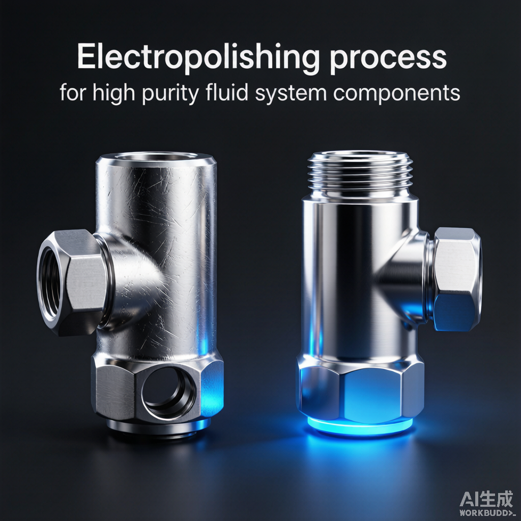
Electropolishing (EP) is a critical surface treatment process for fluid system components used in semiconductor, pharmaceutical, and aerospace applications. By removing a controlled layer of material through electrochemical dissolution, EP produces an exceptionally smooth, clean, and passivated surface that minimizes particle generation, outgassing, and contamination. This article examines the science, process, and quality verification of electropolishing for high-purity fluid system components.
1. Electropolishing Principles
Electropolishing is the reverse of electroplating. The workpiece is the anode in an electrolytic cell. Metal is selectively dissolved from surface peaks where current density is highest, resulting in progressive surface smoothing and micro-burr removal.
- Anodic dissolution: metal ions detach from workpiece surface into electrolyte
- Preferential removal: peaks dissolve faster than valleys due to current concentration
- Oxide layer formation: enriched chromium oxide passivation layer enhances corrosion resistance
- Smoothing ratio: typically removes 0.0005-0.002 inch (12-50 microns) of material
- Surface finish improvement: Ra can be reduced by 50% or more from the pre-polish condition
Figure 1: Electropolishing process comparison showing surface finish improvement
2. Comparison: EP vs Mechanical Polish (MP)
Mechanical polishing uses abrasive media to reduce surface roughness, while electropolishing uses electrochemical dissolution. The two methods produce fundamentally different surface characteristics that affect purity performance.
| Characteristic | Mechanical Polish (MP) | Electropolish (EP) |
|---|---|---|
| Ra achievable | 8-15 microinch (0.2-0.4 micron) | 2-5 microinch (0.05-0.13 micron) |
| Surface structure | Compressed, smeared metal layer | Stress-free, crystalline structure |
| Embedded abrasives | Possible contamination | None (no abrasive contact) |
| Corrosion resistance | Moderate improvement | Significant enhancement |
| Chromium enrichment | Minimal | High (passivation layer) |
| Micro-burr removal | Ineffective | Effective |
| Cost | Lower | Higher (process complexity) |
3. EP Process Parameters
The quality and consistency of electropolishing depend on precise control of electrolyte composition, temperature, current density, and immersion time. Each parameter must be optimized for the specific alloy and component geometry.
3.1 Electrolyte Composition
- Standard electrolyte: sulfuric acid (48%) and phosphoric acid (43%) mixture
- Additives: glycerin or ethylene glycol for viscosity and surface finish control
- Temperature control: 43-65 C for optimal ionic conductivity and surface finish
- Current density: 200-800 A/ft2 (22-86 A/dm2) depending on alloy and surface area
- Immersion time: 5-30 minutes, calibrated for target material removal depth
3.2 Process Sequence
| Step | Process | Duration | Purpose |
|---|---|---|---|
| 1 | Pre-clean (alkaline ultrasonic) | 10 min | Remove oils and contaminants |
| 2 | Rinse (DI water) | 2 min | Remove cleaning residue |
| 3 | Electropolish | 10-20 min | Remove surface material and smooth |
| 4 | Rinse (DI water) | 3 min | Remove electrolyte residue |
| 5 | Passivation (nitric acid) | 20 min | Enhance oxide layer |
| 6 | Final rinse (hot DI water) | 2 min | Remove passivation residue |
| 7 | Dry (clean N2 blow) | 5 min | Remove moisture, prevent water spots |
4. Quality Verification Methods
Electropolished surfaces must be verified against defined acceptance criteria. Multiple measurement techniques confirm surface finish quality, material removal depth, and cleanliness levels.
| Parameter | Measurement Method | Acceptance Criteria |
|---|---|---|
| Surface roughness (Ra) | Profilometer (contact or optical) | Ra <= 5 microinch (0.13 micron) |
| Material removal | Before/after weight or dimensional | 0.0005-0.002 inch (12-50 micron) |
| Surface chemistry | XPS or EDS analysis | Cr/Fe ratio > 1.5 (passivated) |
| Particle count | Liquid particle counter | Class 100 cleanroom compatible |
| Residual hydrocarbon | FTIR or solvent extraction | < 1 mg/m2 |
5. Component Design for EP
Component design affects electropolishing quality. Sharp internal corners, blind holes, and overlapping features can trap electrolyte gas bubbles, creating uneven polishing. Design for electropolishing (DFEP) principles help achieve uniform results.
- Avoid sharp internal corners; provide minimum 0.5 mm radii where possible
- Design blind holes with adequate venting for gas evacuation
- Minimize deep narrow slots where electrolyte circulation is restricted
- Provide tooling features (mounting points) for electrical contact and orientation
- Consider masking requirements for areas that must not be polished
6. Cleanroom Assembly and Packaging
After electropolishing, components for UHP service must be handled, assembled, and packaged in controlled cleanroom environments to prevent recontamination. The cleanliness level achieved during EP can be lost through improper post-process handling.
- Assemble EP components in ISO Class 5 (Class 100) or better cleanroom environment
- Use cleanroom-compatible gloves, tools, and workstation surfaces
- Purge assembled components with filtered UHP nitrogen before packaging
- Seal in double-bagged cleanroom packaging with nitrogen backfill
- Label with process lot number, EP date, and cleanliness certification level
7. Industry Applications
Electropolished components are essential in applications where surface contamination directly impacts product quality, safety, or reliability. Key industries and their EP requirements are summarized below.
| Industry | Application | EP Requirement |
|---|---|---|
| Semiconductor | UHP gas delivery tubing and fittings | Ra <= 3 microinch, UHP certified |
| Pharmaceutical | Sanitary tubing and process connections | Ra <= 4 microinch, FDA compliant |
| Aerospace | Fuel and hydraulic system fittings | Ra <= 5 microinch, reduced friction |
| Food and beverage | Sanitary process piping | Ra <= 4 microinch, CIP compatible |
| Nuclear | Reactor cooling system components | Ra <= 5 microinch, low cobalt |
Source: FITOK Technical Reference