
Industrial Heat Exchanger Selection and Maintenance Guide
By Nick Li · August 10, 2026 · Technical Articles
A Comprehensive Technical Reference for Shell-and-Tube, Plate, and Air-Cooled Heat Exchangers
1. Introduction
Heat exchangers are among the most widely used equipment in process industries, responsible for transferring thermal energy between two or more fluids at different temperatures. From oil refineries and petrochemical plants to power generation and food processing, heat exchangers play a critical role in energy efficiency, process optimization, and operational safety. Selecting the right heat exchanger type, sizing it correctly, and maintaining it throughout its service life are essential skills for any process or mechanical engineer.
This guide provides a structured approach to heat exchanger selection, design considerations, common failure modes, and preventive maintenance strategies. It covers the three most common types—shell-and-tube, plate, and air-cooled—and offers practical recommendations drawn from industry best practices.
2. Common Heat Exchanger Types
2.1 Shell-and-Tube Heat Exchangers
Shell-and-tube heat exchangers are the workhorse of the process industry. They consist of a bundle of tubes enclosed within a cylindrical shell. One fluid flows through the tubes (tube side), while the other flows across the tube bundle (shell side). Their robust construction, ability to handle high pressures and temperatures, and relative ease of cleaning make them suitable for a wide range of applications.
- Typical applications: Oil refinery crude preheating, power plant feedwater heaters, refrigeration condensers
- Advantages: High pressure capability, wide temperature range, mechanical robustness, easy tube-side cleaning
- Limitations: Lower heat transfer coefficient compared to plate type, larger footprint, higher weight
2.2 Plate Heat Exchangers (PHE)
Plate heat exchangers use corrugated metal plates stacked together to form flow channels. Gaskets or brazed joints seal the plates, and fluids alternate between adjacent channels. PHEs achieve very high heat transfer coefficients due to turbulent flow induced by plate corrugation patterns.
- Typical applications: HVAC systems, food and beverage pasteurization, district heating
- Advantages: Compact size, high heat transfer efficiency, easy capacity expansion by adding plates
- Limitations: Pressure and temperature limits set by gasket material, prone to fouling with viscous fluids, harder to clean internally
2.3 Air-Cooled Heat Exchangers (ACHE)
Air-cooled heat exchangers use ambient air as the cooling medium, blown or drawn across finned tube bundles by fans. They eliminate the need for cooling water, making them ideal for arid regions or locations where water is scarce or expensive.
- Typical applications: Natural gas compressor stations, petrochemical condensers, engine cooling
- Advantages: No water consumption, low environmental impact, reduced fouling from water-side scaling
- Limitations: Large footprint, performance depends on ambient temperature, higher initial cost for large units
3. Selection Criteria and Key Parameters
Selecting the appropriate heat exchanger type requires evaluating multiple process parameters. The table below summarizes the key factors and their impact on the selection process:
| Parameter | Shell-and-Tube | Plate (PHE) | Air-Cooled |
|---|---|---|---|
| Max Pressure (bar) | Up to 300+ | Up to 25 (gasketed) | Up to 500 |
| Max Temperature (°C) | Up to 600 | Up to 180 (EPDM) | Up to 300 |
| Heat Transfer Coefficient (W/m²K) | 500–1500 | 3000–7000 | 300–800 |
| Fouling Tolerance | High | Low–Medium | Medium |
| Footprint | Large | Compact | Very Large |
| Maintenance Difficulty | Moderate | Easy (plate access) | Moderate |
| Capital Cost | Medium | Low–Medium | High |
| Best For | High P/T, fouling service | Clean fluids, close approach | Water-scarce areas |
4. Design Considerations
4.1 LMTD and Effectiveness (ε-NTU) Methods
The Log Mean Temperature Difference (LMTD) method is the most commonly used approach for sizing heat exchangers. It accounts for the non-linear temperature change along the heat transfer surface. For complex flow arrangements (cross-flow, multi-pass), the Correction Factor (F) must be applied. Alternatively, the ε-NTU (Effectiveness–Number of Transfer Units) method is preferred when the outlet temperatures are unknown and the exchanger effectiveness needs to be evaluated.
4.2 Pressure Drop Considerations
Pressure drop directly impacts pumping power and operating cost. As a rule of thumb:
- Tube side: Allowable pressure drop of 0.35–0.70 bar for liquids, 0.05–0.10 bar for gases
- Shell side: Target 0.20–0.60 bar for liquids; baffle cut and spacing are key variables
- Plate side: Typically 0.30–0.50 bar per pass
Excessive pressure drop wastes energy, while insufficient pressure drop may indicate low velocity and poor heat transfer. A balanced design optimizes both.
4.3 Fouling Factor
Fouling adds thermal resistance and reduces heat transfer over time. Typical fouling factors range from 0.0001 m²K/W for clean water to 0.0009 m²K/W for heavy hydrocarbons. Over-specifying fouling factors leads to oversized equipment with low velocity that actually accelerates fouling. A best practice is to design with moderate fouling factors and implement effective cleaning cycles.
5. Shell-and-Tube Heat Exchanger Structure
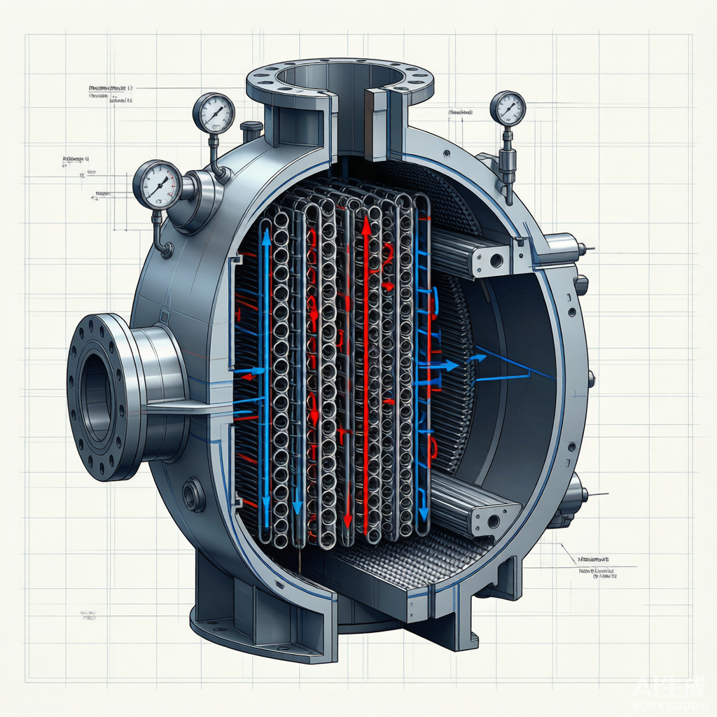
The figure below illustrates the internal structure of a typical shell-and-tube heat exchanger, showing the tube bundle, baffles, and flow paths for both shell-side and tube-side fluids:
Figure 1: Cross-section of a shell-and-tube heat exchanger showing tube bundle, baffles, and fluid flow paths
6. Maintenance and Troubleshooting
6.1 Common Failure Modes
| Failure Mode | Root Cause | Detection Method | Corrective Action |
|---|---|---|---|
| Tube leakage | Corrosion, erosion, vibration fatigue | Hydrostatic test, eddy current testing | Tube plugging or replacement |
| Gasket failure | Aging, thermal cycling, over-torque | Visual inspection, pressure drop increase | Gasket replacement, bolt re-torque |
| Fouling/scaling | Low velocity, high hardness water, particulates | Performance decline, pressure drop increase | Chemical cleaning, mechanical brushing |
| Baffle damage | Flow-induced vibration, tube bundle movement | Vibration analysis, bundle inspection | Weld repair, baffle replacement |
| Tube vibration | Acoustic resonance, inadequate support | Vibration monitoring, noise survey | Anti-vibration inserts, baffle adjustment |
6.2 Preventive Maintenance Schedule
A structured preventive maintenance program extends equipment life and prevents unplanned shutdowns. The following schedule is recommended for shell-and-tube exchangers in typical process service:
- Daily: Monitor inlet/outlet temperatures and pressure drops; log deviations from baseline
- Weekly: Visual inspection for leaks, flange tightness, and insulation integrity
- Monthly: Sample tube-side and shell-side fluids for corrosion indicators (Fe, Cl⁻, pH)
- Quarterly: Perform non-destructive examination (eddy current or ultrasonic) on 10% of tubes
- Annually: Open and inspect tube bundle; clean as needed; re-torque all bolting; perform hydrotest
- Every 3–5 years: Complete tube bundle removal, full cleaning, retubing if wall loss exceeds 30%
6.3 Cleaning Methods
Cleaning strategy depends on the type and severity of fouling:
- Chemical cleaning: Circulate acid or alkaline solutions to dissolve scale and deposits. Best for tube-side fouling in hard-to-reach areas.
- Mechanical cleaning: High-pressure water jetting, rotary brushes, or scrapers. Effective for shell-side and tube-side deposits.
- Online cleaning: Backflushing, sponge ball cleaning systems, or chemical injection while the unit remains in service. Best for preventing rather than removing heavy fouling.
7. Conclusion
Heat exchanger selection and maintenance represent a balance between thermal performance, pressure drop, capital cost, and operational reliability. No single type is universally optimal—each application demands careful evaluation of process conditions, fluid properties, and lifecycle requirements. By following a structured selection methodology and implementing a disciplined preventive maintenance program, engineers can maximize heat exchanger efficiency, extend equipment life, and minimize unplanned downtime.
The key takeaways are: (1) match the exchanger type to the process requirements, (2) design for realistic fouling and pressure drop, (3) monitor performance continuously, and (4) clean before degradation becomes severe. These principles, combined with emerging technologies such as digital twins and predictive analytics, will continue to drive improvements in heat exchanger reliability and energy efficiency across all process industries.
Source: Original technical article generated for blog publication.