
Pressure Regulator Selection and Supply Pressure Effect Analysis
By Nick Li · August 10, 2026 · Technical Articles
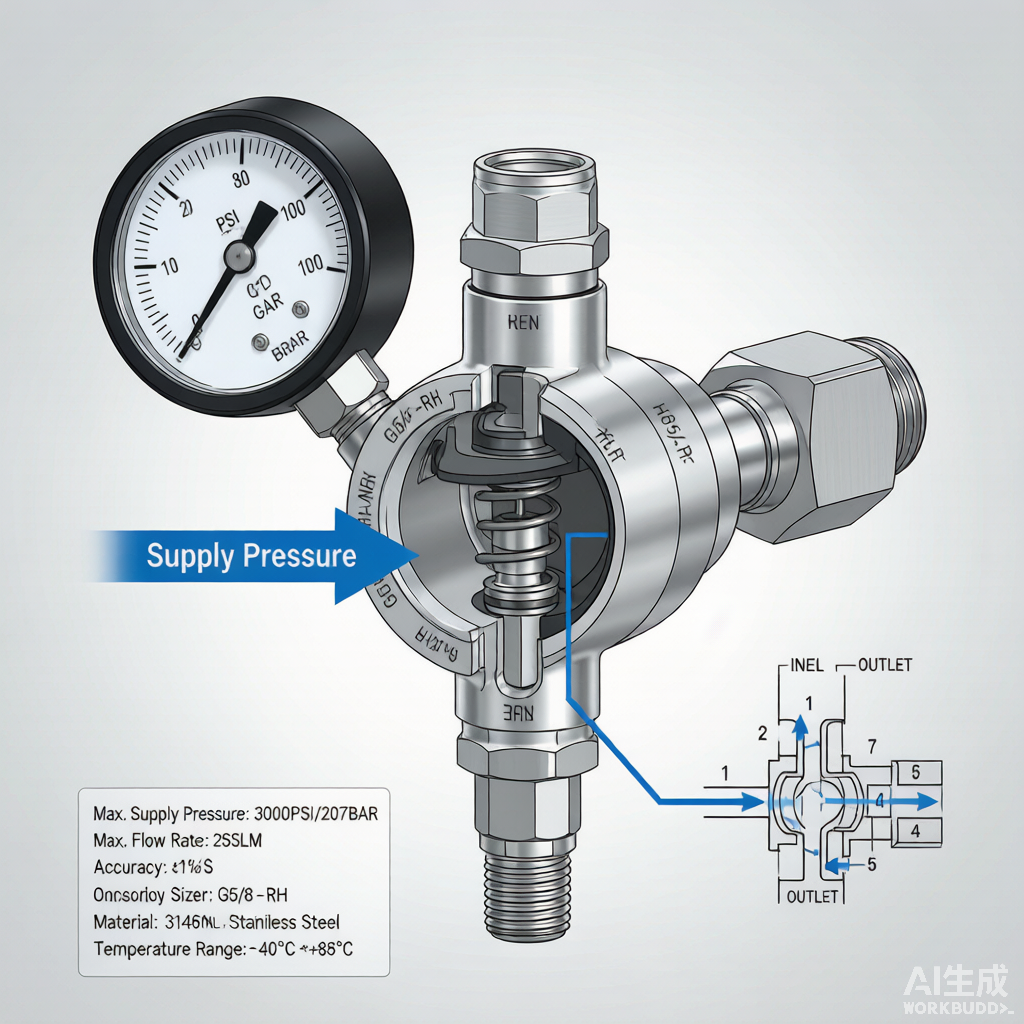
Pressure regulators are critical components in fluid and gas delivery systems, maintaining a stable outlet pressure despite variations in inlet (supply) pressure and downstream flow demand. The Supply Pressure Effect (SPE) is a key performance metric that quantifies how much the outlet pressure changes in response to inlet pressure variations. This article provides a comprehensive guide to pressure regulator selection, with emphasis on SPE minimization for precision applications.
1. Regulator Operating Principles
A pressure regulator uses a sensing element (diaphragm or piston) that responds to outlet pressure changes. The sensing element adjusts the valve opening to maintain the set outlet pressure. The force balance between spring pressure, outlet pressure, and supply pressure determines the valve position.
- Diaphragm type: flexible membrane, high sensitivity, suitable for low to medium pressure
- Piston type: metal piston, higher pressure capability, lower sensitivity
- Loaded type: uses external pressure (air or spring) instead of adjustment spring
- Two-stage: two regulators in series for maximum SPE reduction
- Dome-loaded: external reference pressure for high-flow applications
Figure 1: Precision pressure regulator cross-section showing diaphragm and SPE mechanism
2. Supply Pressure Effect (SPE)
SPE is the ratio of outlet pressure change to inlet pressure change. It is expressed as a percentage or as a ratio (e.g., 1:100 means a 100 psi inlet change causes 1 psi outlet change). Lower SPE values indicate superior pressure regulation.
| Regulator Type | Typical SPE | Application |
|---|---|---|
| Single-stage, spring-loaded | 3-5% | General purpose, non-critical |
| Single-stage, diaphragm | 1-3% | Process gas, moderate precision |
| Two-stage (series) | 0.1-0.5% | High precision, semiconductor gas |
| Pilot-operated | 0.05-0.2% | High flow, high precision |
| Electronic (PID control) | < 0.05% | Ultra-precision, automated systems |
3. Flow Capacity (Cv) Selection
The flow coefficient (Cv) determines the maximum flow rate a regulator can handle while maintaining stable outlet pressure. Undersized regulators cause flow starvation and pressure droop; oversized regulators provide poor control resolution.
- Calculate required Cv from flow rate, inlet pressure, outlet pressure, and gas properties
- Select regulator with Cv 1.5-2x the calculated requirement for margin
- Consider minimum controllable flow for low-flow applications (turn-down ratio)
- Check choked flow conditions: outlet pressure < 0.5x inlet pressure causes sonic flow
- Account for temperature effects on gas viscosity and Cv calculation
4. Material and Seal Selection
Regulator wetted materials must be compatible with the process gas and meet purity requirements. Seal materials affect leak integrity, temperature range, and chemical compatibility.
| Component | Material Options | Selection Criteria |
|---|---|---|
| Body | 316L SS, Brass, Alloy 625 | Pressure, corrosion, purity level |
| Diaphragm | 316L SS, Hastelloy C-22, PCTFE | Pressure range, permeation |
| Seat | PCTFE, PEEK, Vespel, metal | Temperature, cycle life, leakage |
| O-rings | Viton, EPDM, FFKM, silicone | Gas compatibility, temperature |
| Spring | 316 SS, 17-7 PH | Corrosion resistance, fatigue life |
5. Specialty Gas Regulator Design
For semiconductor specialty gas applications, regulators must meet ultra-high-purity requirements with minimal contamination potential. The diaphragm seal design eliminates packings that could leak or generate particles.
- Metal diaphragm: eliminates elastomer permeation, EP finish for UHP service
- Diaphragm seal: no packing, no particle generation, helium leak < 10^-9 atm cc/sec
- Captured vent: safety vent on diaphragm failure for hazardous gas containment
- Electropolished internals: Ra < 5 microinch for minimal surface area and outgassing
- VCR connections: metal face seal inlet/outlet for UHP gas compatibility
6. Two-Stage Regulation Strategy
Two-stage regulation is used when inlet pressure varies significantly (e.g., cylinder pressure decreasing from 2000 to 200 psig over service life). The first stage reduces inlet pressure to an intermediate value, and the second stage provides the final regulated outlet pressure.
| Parameter | Single-Stage | Two-Stage |
|---|---|---|
| SPE | 1-5% | 0.1-0.5% |
| Cost | Lower | Higher |
| Complexity | Simple | Two regulators in series |
| Flow capacity | Same Cv | Same Cv (limited by second stage) |
| Recommended for | Stable inlet pressure | Cylinder gas (decreasing pressure) |
7. Installation and Troubleshooting
Proper installation and maintenance of pressure regulators ensures accurate, reliable performance. Common issues such as creep (rising outlet pressure), droop (outlet pressure drop with flow), and chatter can usually be traced to installation or sizing problems.
- Install upstream filter to prevent seat damage from particulate contamination
- Mount regulator upright to prevent condensate accumulation in sensing chamber
- Never operate above rated inlet pressure or temperature (causes seal damage)
- Check for creep: if outlet pressure rises when downstream valve is closed, inspect seat
- Address droop: if outlet pressure drops significantly with increasing flow, upgrade Cv
- Scheduled diaphragm replacement: every 2-5 years depending on service severity
Source: FITOK Technical Reference