
Reciprocating Compressor Maintenance: Valves, Pistons, and Seals
By Nick Li · August 10, 2026 · Technical Articles
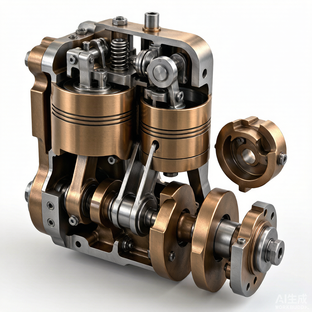
Figure: Cross-sectional view of a reciprocating compressor showing cylinder, piston, valves, and crankshaft assembly
Reciprocating Compressor Overview
Working Principle
The reciprocating compressor operates on a positive displacement principle, executing a suction-compression-discharge cycle within each cylinder for every revolution of the crankshaft. During the suction stroke, the piston moves downward, reducing the pressure inside the cylinder below the inlet line pressure. This pressure differential causes the suction valve to open, allowing process gas to flow into the cylinder bore. As the piston reverses direction and moves upward, the suction valve closes and the trapped gas is compressed. When the cylinder pressure exceeds the discharge line pressure, the discharge valve opens and the compressed gas is expelled. This two-stroke cycle — one for suction and one for compression-discharge — repeats continuously, making the reciprocating compressor one of the most mechanically straightforward yet thermodynamically efficient devices for high-pressure gas applications.
Key Components
A reciprocating compressor comprises several critical components, each engineered to withstand high cyclic loads and maintain gas-tight operation over millions of revolutions:
- Cylinder: The pressure-containing envelope where compression occurs. Cylinders may be single- or double-acting and are typically fitted with removable liners to allow re-boring or replacement without scrapping the entire body.
- Piston: The reciprocating element that displaces gas within the cylinder. Pistons are often fitted with compression rings and rider rings to seal against the cylinder wall and prevent excessive wear.
- Valves: Self-actuating, spring-loaded check valves positioned at the suction and discharge ports. They open and close purely in response to differential pressure across the valve seat.
- Crankshaft: Converts rotational input from the driver (motor or engine) into the reciprocating motion of the piston via the connecting rod. Counterweights on the crankshaft balance inertial forces.
- Connecting Rod: Transmits force between the crankshaft and the crosshead, converting rotary motion to linear reciprocation. It carries both large-end and small-end bearings.
- Crosshead: The pivoting linkage between the connecting rod and the piston rod. It guides the piston rod in a straight line and absorbs side-thrust loads that would otherwise reach the cylinder wall.
Advantages
Reciprocating compressors remain indispensable across oil and gas, petrochemical, and industrial gas sectors due to several inherent advantages:
- High Pressure Ratio Capability: A single-stage reciprocating compressor can achieve pressure ratios of 3:1 to 4:1, and multi-stage configurations can deliver discharge pressures exceeding 10,000 psi (690 bar), far surpassing the limits of dynamic compressors.
- Flexible Capacity: Capacity can be modulated through unloaders, clearance pockets, variable speed drives, or a combination of these methods, allowing efficient turn-down to as low as 10-20% of rated flow without significant loss in efficiency.
- Broad Gas Compatibility: The design accommodates a wide range of molecular weights and gas compositions, making it suitable for hydrogen, natural gas, CO2, and mixed hydrocarbon services.
Valve Maintenance and Failure Analysis
Valve Types
Compressor valves are the most frequently serviced components in a reciprocating unit. Three principal designs dominate the market:
- Plate Valves: Feature one or more flat spring plates that lift off a seat to permit gas flow. They are economical, compact, and widely used in moderate-speed applications up to 600 rpm.
- Ring Valves: Use concentric rings instead of a single plate, allowing independent lifting of each ring. This reduces inertial stress and extends valve life in higher-speed compressors.
- Poppet Valves: Employ individual mushroom-shaped elements, each with its own spring. The streamlined flow path minimizes pressure drop, making them ideal for low-ratio, high-flow services such as pipeline gas transmission.
Common Failures
Valve failures account for the majority of unplanned reciprocating compressor shutdowns. Understanding the failure modes is essential for effective preventive maintenance:
- Spring Fatigue: Cyclic loading at compressor speed causes valve springs to lose tension over time. Fatigued springs result in delayed valve closure, leading to gas backflow and elevated discharge temperatures.
- Plate Cracking: Repeated impact against the valve seat and guard induces fatigue cracking in plate and ring elements. Cracks allow gas leakage even when the valve is nominally closed, reducing volumetric efficiency.
- Carbon Buildup: In lubricated compressors handling hydrocarbon gases, lubricant decomposition at high discharge temperatures forms carbon deposits on valve seats and plates. These deposits prevent proper seating and can cause localized overheating.
Inspection Procedures
A structured valve inspection program should be conducted at every scheduled shutdown or whenever performance indicators suggest valve degradation:
- Visual Inspection: Examine valve plates, rings, springs, and seats for cracks, pitting, erosion, and carbon deposits. Use magnification for hairline cracks that are invisible to the naked eye.
- Leak Testing: Pour a light solvent or kerosene into the assembled valve held horizontally. If the liquid seeps through the seat interface within a few seconds, the valve must be reworked or replaced.
- Lift Measurement: Use a dial indicator to verify that valve element lift matches the manufacturer specification. Excessive lift shortens valve life by increasing impact velocity; insufficient lift chokes flow and raises discharge temperature.
Valve Life Optimization
Extending valve mean time between failures (MTBF) requires attention to material selection, operational parameters, and maintenance discipline:
- Proper Material Selection: Match valve plate material to the gas composition and temperature. PEEK (polyether ether ketone) plates offer excellent impact resistance for corrosive or wet gas service, while metallic plates suit high-temperature applications.
- Correct Lift Setting: Adhere to the manufacturer-specified lift dimension. Aftermarket springs that alter valve dynamics should be avoided unless validated by a rigorous engineering analysis.
- Lubricant Management: In lubricated cylinders, maintain the correct cylinder oil feed rate. Over-lubrication accelerates carbon buildup, while under-lubrication increases wear on valve plates and seats.
Piston and Cylinder Wear
Wear Measurement
Progressive wear of the cylinder bore and piston rings is inevitable in reciprocating compressors. Quantifying this wear through scheduled measurement allows maintenance teams to plan overhauls before performance degrades catastrophically:
- Bore Taper: Measure the cylinder internal diameter at multiple planes along the stroke length using a bore gauge. A taper exceeding 0.002 inch per inch of bore diameter (or the manufacturer limit) indicates the need for re-boring or liner replacement.
- Piston-to-Cylinder Clearance: Determine the diametral clearance between the piston and the cylinder wall. Excessive clearance causes piston slap, accelerates ring wear, and can lead to rod loading asymmetry.
Ring Wear
Piston rings are the primary seal between the compression and crank-end sides of the piston. Their condition directly affects compressor throughput and efficiency:
- End Gap Check: Place each ring squarely in the cylinder bore at the bottom of the stroke and measure the butt gap with a feeler gauge. Compare the reading to the manufacturer specification; an enlarged gap indicates ring wear and gas blow-by.
- Side Clearance Check: Measure the axial clearance between the ring and its groove in the piston. Excessive side clearance causes ring flutter and accelerated groove widening, while insufficient clearance can ring-bind at operating temperature.
Scoring and Galling Causes
Scoring and galling are severe wear mechanisms that can rapidly destroy a cylinder liner and piston assembly. The principal causes include:
- Inadequate Lubrication: Insufficient cylinder oil feed or incorrect oil viscosity leads to metal-to-metal contact between rings and the cylinder wall, causing adhesive wear and material transfer.
- Contamination: Ingestion of particulate matter — dust, pipe scale, or debris — acts as an abrasive between sliding surfaces, producing circumferential scoring marks that compromise the gas seal.
- High Discharge Temperature: Elevated temperatures from faulty valves or excessive compression ratios degrade the lubricant film and reduce its load-carrying capacity, promoting galling on aluminum or cast-iron pistons.
Packing and Seal Maintenance
Packing Ring Types
The pressure packing assembly seals the piston rod as it passes through the cylinder head, preventing high-pressure gas from leaking into the crankcase. Two broad categories of packing rings are used:
- Lubricated Packing Rings: Designed for service with a continuous supply of cylinder lubricant. The lubricant forms a micro-film between the ring and rod, reducing friction and wear. These rings are typically made from metallic or filled-PTFE materials and suit high-pressure, continuous-duty applications.
- Non-Lubricated Packing Rings: Engineered for oil-free services where process contamination by lubricant is unacceptable. They rely on self-lubricating materials such as glass-filled or carbon-filled PTFE. Non-lubricated packing generally has a shorter service life and requires more frequent replacement intervals.
Leakage Detection and Acceptable Limits
Some leakage through the packing is normal, but excessive leakage signals ring wear or damage. Detection and monitoring methods include:
- Visual and Auditory Inspection: A hissing sound or visible gas vapor at the packing vent indicates active leakage. The packing vent line should be routed to a safe disposal point.
- Leak Rate Measurement: Use a calibrated flow meter or a timed bubble test on the vent line. Acceptable leak rates vary by service but are typically below 0.5 scfm for standard process compressors; consult OEM specifications for exact limits.
- Trending: Track leak rate over time on a trend chart. A sudden increase suggests a broken ring or damaged rod surface, while a gradual rise indicates progressive wear that should be addressed at the next scheduled shutdown.
Packing Replacement Procedure
When leak rates exceed acceptable limits, the packing case must be removed and the rings replaced. A disciplined procedure ensures a reliable seal on the first start-up:
- Step 1 — Depressurize and Isolate: Verify that the cylinder is fully depressurized and locked out per the facility lockout-tagout (LOTO) procedure before beginning disassembly.
- Step 2 — Remove Packing Case: Withdraw the packing case from the cylinder head bore. Document the orientation and stacking order of each ring set to ensure correct reassembly.
- Step 3 — Inspect Piston Rod: Check the rod for scoring, taper, and surface hardness loss. A worn or grooved rod will rapidly destroy new packing rings; if the rod diameter is out of tolerance, re-chrome or replace it.
- Step 4 — Install New Rings: Lubricate each ring lightly and install them in the correct order with proper tangential or radial cut orientation per the OEM drawing.
- Step 5 — Torque and Test: Reinstall the packing case, torque the flange bolts in a star pattern to the specified value, and conduct a slow-rotation leak check before returning the unit to full load.
Lubrication System
Cylinder Lubrication
Cylinder lubrication reduces friction between the piston rings and cylinder wall, minimizes wear on packing rings, and provides a seal that helps contain gas pressure. The correct feed rate is critical to both reliability and economy:
- Feed Rate Calculation: The required cylinder oil feed rate (pints per day) is calculated from the total cylinder bore surface area swept per day, multiplied by an oil film factor (typically 1/2 to 1 pint per million square feet of swept surface, adjusted for gas composition and pressure). OEM guidelines should always be consulted for the specific compressor model.
- Distribution: Ensure that each lubrication point — typically at the packing, mid-bore, and top of the cylinder — receives the correct proportion of the total feed. Blockages in distribution lines cause dry spots and localized wear.
- Adjustment: Start with the OEM-recommended rate and adjust based on inspection findings. If ring wear is accelerating, increase the feed slightly; if excessive carbon buildup appears on valves, reduce it.
Frame Lubrication
The frame (crankcase) lubrication system supplies pressurized oil to the main bearings, crankpin bearings, crosshead pin, and crosshead guides. Its reliability is fundamental to the mechanical integrity of the compressor:
- Oil Pump: A gear-type or gerotor pump, typically driven by the main shaft or an auxiliary motor, circulates oil through the frame. Monitor pump discharge pressure and replace the pump if pressure drops below the OEM minimum.
- Filter: A full-flow filter (typically 10-25 micron rating) removes particulates from the circulating oil. Replace the filter element when the differential pressure across the housing reaches the manufacturer-specified change-out point.
- Oil Cooler: A shell-and-tube or air-cooled heat exchanger maintains frame oil temperature within the 120-160°F (49-71°C) range. Fouled cooler tubes raise oil temperature and accelerate lubricant degradation.
Oil Grades and Change Intervals
Selecting the correct lubricant and adhering to a disciplined oil change schedule are among the most impactful maintenance decisions for a reciprocating compressor:
- Cylinder Oil: Use a compounded mineral or synthetic oil with the viscosity and additives specified for the gas composition and discharge temperature. For high-pressure hydrocarbon service, ISO VG 100-220 with anti-wear additives is common.
- Frame Oil: An R&O (rust and oxidation) inhibited turbine oil, typically ISO VG 68-100, is standard for frame lubrication. Consult the OEM for approved lubricant lists.
- Change Interval: Change frame oil every 8,000 operating hours or annually, whichever comes first, and perform oil analysis at 1,000-hour intervals to detect early signs of bearing wear, coolant ingress, or oxidation.
Preventive Maintenance Schedule
A well-structured preventive maintenance (PM) program is the backbone of reciprocating compressor reliability. The schedule below organizes tasks by frequency, from daily walk-around checks to comprehensive annual overhauls. Adhering to this cadence minimizes unplanned downtime, extends component life, and protects the capital investment in the equipment.
Maintenance Checklist by Frequency
| Frequency | Maintenance Task | Description |
|---|---|---|
| Daily | Visual walk-around inspection | Check for oil leaks, unusual noise, vibration, and gas leaks at flanges and packing vents. |
| Daily | Lubricant level check | Verify frame oil level sight glass and cylinder lubricant reservoir level are within range. |
| Daily | Discharge temperature monitoring | Record stage discharge temperatures; investigate any reading exceeding OEM high-limit alarm. |
| Daily | Packing vent leak observation | Inspect packing vent lines for abnormal gas flow or audible hissing. |
| Monthly | Valve temperature survey | Use an infrared thermometer to compare suction and discharge valve cover temperatures; deviations indicate leaking valves. |
| Monthly | Oil sample analysis | Draw a frame oil sample and send to the lab for spectrometric analysis of wear metals, viscosity, and water content. |
| Monthly | Vibration data collection | Collect baseline vibration readings at main bearings, crosshead, and cylinder; trend the data for changes. |
| Monthly | Filter differential pressure check | Record the frame oil filter differential pressure; replace the element if it reaches the change-out threshold. |
| Quarterly | Piston rod runout measurement | Measure rod runout with a dial indicator; exceedance of OEM limits signals crosshead or rod alignment issues. |
| Quarterly | Safety device function test | Test all pressure relief valves, low-oil-pressure shutdown, and high-temperature trips for proper actuation. |
| Annually | Valve removal and inspection | Remove all suction and discharge valves for bench inspection, leak test, and component replacement as needed. |
| Annually | Cylinder bore measurement | Measure bore taper and piston-to-cylinder clearance at top, mid, and bottom of stroke; compare to baseline. |
| Annually | Packing ring inspection | Remove the packing case, inspect rings for wear, measure the piston rod for scoring and taper, and replace rings as required. |
| Annually | Frame oil and filter change | Drain and refill frame oil, replace the full-flow filter element, and clean the suction strainer. |
| Every 3-5 years | Major overhaul | Disassemble the compressor to the frame, inspect crankshaft journals, bearings, crosshead, and connecting rods; re-bore or replace cylinder liners as indicated by wear data. |
Source: Compressor Maintenance Forum