
Reciprocating Compressor Structural Design and Operating Principles
By Nick Li · August 10, 2026 · Technical Articles
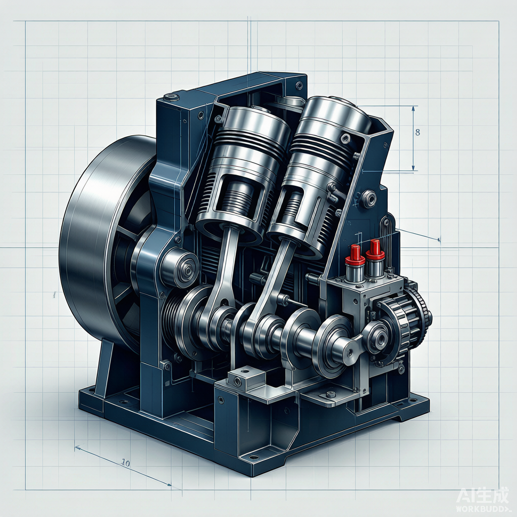
Understanding the structural design and operating principles of reciprocating compressors is fundamental for engineers, technicians, and maintenance personnel. This article provides a detailed examination of the key components, their functions, and the thermodynamic principles that govern compressor operation.
1. Overall Architecture
A reciprocating compressor consists of a power frame, cylinder assembly, and auxiliary systems. The frame houses the crankshaft, connecting rods, and crossheads, converting rotational motion from the driver into linear reciprocating motion at the pistons.
- Frame: cast iron or fabricated steel structure housing running gear
- Cylinders: machined cast iron or forged steel, containing compression chambers
- Pistons: aluminum, cast iron, or steel depending on pressure rating
- Valves: automatic spring-loaded plate or ring type
- Packings: multi-ring sealing assembly at rod penetration
2. Crank Mechanism and Force Transmission
The crank mechanism converts the rotational torque from the driver into the linear force that compresses gas. The connecting rod transfers force between the crank pin (rotating) and the crosshead pin (reciprocating), while the crosshead guides the piston rod along the cylinder axis.
2.1 Key Force Path
| Component | Function | Design Consideration |
|---|---|---|
| Crankshaft | Converts torque to reciprocating motion | Forged steel, journal hardness > 250 HB |
| Connecting rod | Links crank pin to crosshead | I-beam section, bronze bushings |
| Crosshead | Guides linear motion, transfers load | Replaceable shoes, hardened guides |
| Piston rod | Connects crosshead to piston | High tensile steel, surface nitrided |
| Piston | Compresses gas in cylinder | Lightweight, multi-ring grooved |
3. Cylinder Design and Compression Chambers
Cylinders are designed for specific pressure ranges and gas compositions. They may be single-acting (compression on one side only) or double-acting (compression on both sides). Multi-stage compressors use progressively smaller cylinder bores to handle increasing pressure ratios.
- Cylinder bore: precision machined and honed for ring sealing
- Water jackets: integral cooling passages for temperature control
- Valve ports: sized for optimal gas velocity (typically 30-50 m/s)
- Clearance volume: minimized for efficiency but maintained for valve function
- Cylinder lubrication: forced feed or non-lubricated (PTFE-based designs)
Figure 1: Cross-section diagram showing reciprocating compressor internal structure
4. Compression Thermodynamics
The compression process follows thermodynamic principles. Understanding the P-V relationship is essential for evaluating compressor efficiency and diagnosing performance issues.
4.1 Theoretical Compression Cycle
The ideal compression cycle consists of four phases: suction, compression, discharge, and expansion. The actual cycle deviates from the ideal due to valve losses, clearance volume effects, and heat transfer.
| Phase | Process | P-V Characteristic |
|---|---|---|
| Suction | Gas drawn in at suction pressure | Volume increases at constant pressure |
| Compression | Gas compressed to discharge pressure | Volume decreases, pressure rises |
| Discharge | Compressed gas expelled | Volume decreases at constant pressure |
| Expansion | Trapped gas expands | Volume increases, pressure drops |
4.2 Compression Efficiency Metrics
- Volumetric efficiency: actual capacity / theoretical displacement volume
- Isentropic efficiency: ideal isentropic work / actual indicated work
- Mechanical efficiency: indicated power / brake power input
- Overall efficiency: isentropic x mechanical efficiency
- Specific energy consumption: kW per (m3/min) of free air delivered
5. Valve Design and Operation
Compressor valves are automatic, pressure-actuated devices that control gas flow into and out of the cylinder. Their design directly impacts compressor efficiency, reliability, and maintenance frequency.
- Plate valves: thin spring steel plates, suitable for clean gas and moderate speeds
- Ring valves: concentric rings, good for high-speed and high-pressure service
- Poppet valves: mushroom-shaped elements, excellent flow characteristics
- Channel valves: flexible strip elements, suited for low-speed applications
- Valve lift: optimized to balance flow area against impact velocity
6. Lubrication System Architecture
The lubrication system supplies oil to bearings, crossheads, and cylinder walls, reducing friction, removing heat, and flushing wear particles. Two separate systems are typically employed: force-feed frame lubrication and cylinder lubrication.
| System | Components | Oil Type | Pressure |
|---|---|---|---|
| Frame lubrication | Gear pump, filter, cooler, main bearings | Turbine/ISO VG 150 | 2-4 bar |
| Cylinder lubrication | Lubricator, check valves, distribution lines | Compounded cylinder oil | Feed rate controlled |
| Packing lubrication | Mister or force-feed to packing | Synthetic or mineral | Low pressure |
7. Control and Capacity Regulation
Reciprocating compressor capacity must be regulated to match process demand. Several methods are employed, each with different efficiency and complexity characteristics.
- Step control: unload cylinders by holding suction valves open (0%, 50%, 100%)
- Clearance pocket control: add variable clearance volume to reduce capacity
- Variable speed drive: adjust motor speed for continuous capacity control
- Bypass control: recycle discharge gas to suction (simple but inefficient)
- Start-stop control: for small units with intermittent demand
Source: Compressor Technology Editorial Reference