
Valve Manifold Box and Panel Design for Specialty Gas Distribution
By Nick Li · August 10, 2026 · Technical Articles
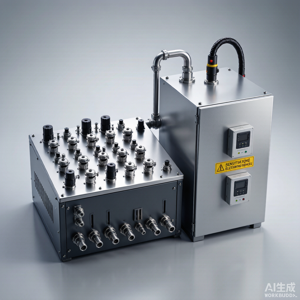
Valve Manifold Boxes (VMB) and Valve Manifold Panels (VMP) are critical infrastructure components in semiconductor gas distribution systems. VMBs handle hazardous and specialty gases with full containment, exhaust, and purge capabilities, while VMPs manage inert gas distribution with centralized control. This article examines the design principles, safety features, and operational requirements for these essential gas delivery system components.
1. VMB vs VMP: Application Distinction
While both VMBs and VMPs serve as gas distribution control points, their applications, safety requirements, and design features differ significantly based on the hazard level of the gases they handle.
| Feature | VMB (Valve Manifold Box) | VMP (Valve Manifold Panel) |
|---|---|---|
| Gas type | Hazardous, toxic, pyrophoric, corrosive | Inert, non-hazardous |
| Containment | Sealed enclosure with exhaust | Open panel, no enclosure |
| Exhaust system | Required (per SEMI S2) | Not required |
| Gas detection | Required (compatible sensor) | Not typically required |
| Purge capability | Required (N2 or inert) | Optional |
| Interlocks | Required (exhaust, detector, EMO) | Optional |
| Typical location | Sub-fab or gas cabinet room | Sub-fab or chase area |
Figure 1: VMB with integrated valves, regulators, filters, and monitoring for semiconductor gas distribution
2. VMB Design Architecture
A VMB integrates multiple gas distribution functions into a single safety-rated enclosure. The design must satisfy SEMI S2 safety guidelines while providing reliable gas distribution and emergency response capability.
- Stainless steel enclosure with continuous exhaust (typically 200-400 CFM)
- Process gas lines: 316L EP tubing with VCR metal face seal connections
- Purge gas lines: UHP nitrogen for safe line evacuation before maintenance
- Exhaust port: routed to facility abatement system for toxic gas treatment
- Access doors: interlocked to shut gas on door opening (LOTO compliant)
- EMO (Emergency Maintenance Off): immediate gas shutdown and purge activation
3. Integrated Gas System (IGS) Concept
The Integrated Gas System (IGS) approach integrates valves, regulators, filters, and monitoring instruments into a single, pre-engineered manifold assembly. IGS design reduces footprint, minimizes leak points, and improves system cleanliness compared to individually assembled components.
- Modular block design: multi-port valve body eliminates inter-component connections
- Reduced internal volume: faster purge cycles and lower gas waste
- Fewer leak points: up to 65% reduction in potential leak paths vs conventional assembly
- Surface finish: EP on all wetted surfaces for UHP compatibility
- Integrated monitoring: pressure, flow, and gas detection in one assembly
4. Safety Interlock Systems
VMB safety interlocks prevent hazardous gas release during maintenance, power failure, or abnormal conditions. The interlock logic is implemented in a safety-rated PLC (SIL2 minimum) per IEC 61511.
| Interlock | Trigger Condition | System Response |
|---|---|---|
| Door interlock | VMB access door opens | Close process gas valves, open purge |
| Exhaust failure | Exhaust flow sensor below threshold | Shut process gas, alarm |
| Gas detection | Sensor exceeds alarm setpoint | Shut gas, purge, evacuate, alarm |
| Power failure | Loss of facility power | Fail-close process valves (spring-return) |
| Manual EMO | Operator presses emergency stop | Immediate gas shutoff, purge on |
| Cylinder pressure | Pressure below minimum threshold | Switch to backup cylinder, alarm |
5. Purge Sequencing
Purge sequences safely remove hazardous process gas from lines before maintenance. The sequence must be carefully designed to minimize gas waste while ensuring complete removal of hazardous gas to safe levels.
- Evacuation: close process gas source, vent line to exhaust (reduce to < 10% LEL)
- Cycle purge: alternate N2 pressurize and vent to exhaust (3-5 cycles minimum)
- Continuous purge: low flow N2 during maintenance to prevent back-contamination
- Evacuation verification: gas detector confirms hazardous gas < PEL before door unlock
- Post-maintenance purge: before gas reintroduction, purge line with process gas
6. Gas Detection Integration
Continuous gas detection within the VMB is critical for early leak detection and personnel safety. The detection system must be compatible with the specific gases being handled.
| Gas Type | Detection Method | Alarm Setpoint |
|---|---|---|
| SiH4 (pyrophoric) | FTIR or electrochemical | 0.5 ppm (STEL) |
| AsH3 (toxic) | Electrochemical | 0.05 ppm (TWA) |
| H2 (flammable) | Catalytic bead or thermal conductivity | 1% LEL (4000 ppm) |
| Cl2 (corrosive) | Electrochemical | 0.5 ppm (STEL) |
| NF3 (toxic) | FTIR | 10 ppm (TWA) |
7. VMP Design for Inert Gas Distribution
VMPs distribute inert gases (N2, Ar, He, CDA) from a central source to multiple points of use. While they don’t require containment, VMPs still need careful design for flow balance, pressure management, and maintenance access.
- Source connection: bulk gas supply (liquid tank or tube trailer) or cylinder bank
- Main isolation valve: full-bore ball valve for maintenance isolation
- Pressure regulation: single-stage regulator per distribution line
- Individual line isolation: needle valve for each POU for flow regulation
- Filter: coalescing or particulate filter at panel inlet (0.01 micron final)
- Pressure monitoring: gauge or transmitter on each distribution line
- Design for easy maintenance: label all lines, provide access for tool use
Source: FITOK Technical Reference