
Valve Selection for Oil and Gas Processing Applications
By Nick Li · August 10, 2026 · Technical Articles
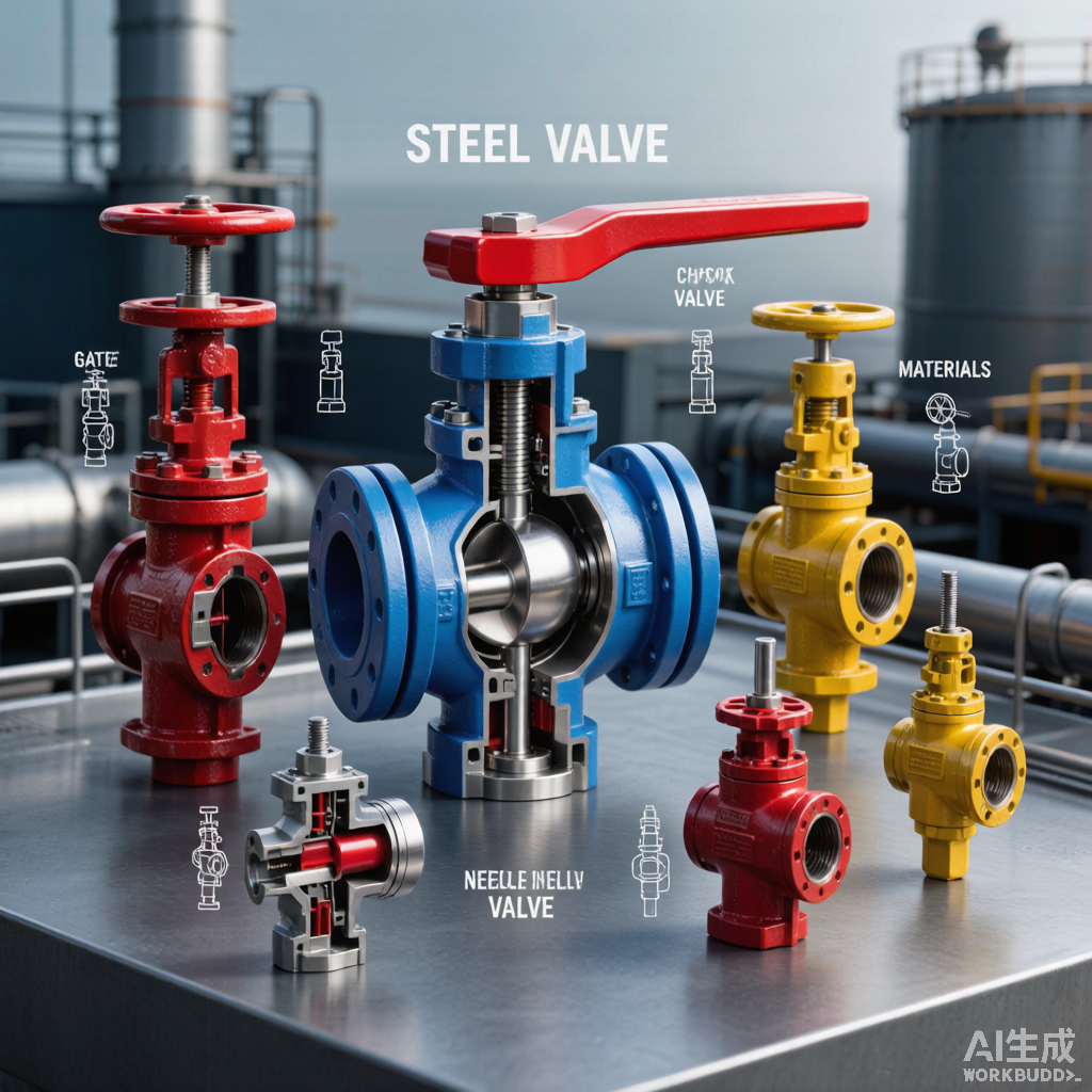
Valve selection in oil and gas processing demands careful consideration of process conditions, fluid characteristics, safety requirements, and regulatory standards. The wrong valve choice can lead to leaks, process upsets, equipment damage, and safety incidents. This article provides a systematic framework for valve selection across common oil and gas applications.
1. Valve Type Overview
Different valve types serve different functions in process systems. Understanding the strengths and limitations of each type is the foundation of effective valve selection.
| Valve Type | Primary Function | Advantages | Limitations |
|---|---|---|---|
| Ball valve | Isolation (on/off) | Full bore, fast operation, tight shutoff | Not for throttling, limited temp range |
| Gate valve | Isolation (on/off) | Low pressure drop, full bore | Slow operation, not for throttling |
| Globe valve | Flow regulation | Good throttling, repairable seat | High pressure drop, slow operation |
| Needle valve | Fine flow control | Precise regulation, compact | Low flow capacity, limited bore |
| Check valve | Backflow prevention | Automatic, no actuation needed | Water hammer risk, swing types |
Figure 1: Industrial valve selection guide showing various valve types and cross-sections
2. Material Selection for Process Compatibility
Oil and gas process fluids range from sweet natural gas to highly corrosive sour gas containing H2S, CO2, and chlorides. Material selection must address both general and localized corrosion mechanisms.
2.1 Pitting Resistance Equivalent Number (PREN)
PREN is a calculated value based on chromium, molybdenum, and nitrogen content that predicts pitting corrosion resistance. Higher PREN values indicate better resistance to chloride-induced pitting.
| Material | PREN | CPT (C) | Typical Service |
|---|---|---|---|
| 316 SS | 24-26 | 15-20 | Sweet service, moderate corrosion |
| Duplex 2205 | 34-38 | 35-45 | Moderate chloride, sour service |
| Super Duplex 2507 | 42-48 | 60-70 | High chloride, severe sour |
| Alloy 625 | 48-54 | 70+ | Extreme corrosion, high temp |
| Alloy 825 | 30-36 | 25-35 | Acid gas, sulfuric acid service |
2.2 NACE Compliance
For sour gas service (H2S-containing), NACE MR0175/ISO 15156 defines material requirements to prevent sulfide stress cracking (SSC). All pressure-containing components must comply with this standard.
- Material hardness must not exceed 22 HRC for carbon and low-alloy steels
- Austenitic stainless steel maximum hardness: 22 HRC (316 SS in sour service)
- Super duplex 2507: maximum hardness 28 HRC, maximum service temperature 232 C
- Verify each component has NACE-compliant material certification (MTR/3.1)
- Consider SSC severity region per NACE diagram based on H2S partial pressure and pH
3. Valve Design Features
Beyond material selection, valve design features determine performance in demanding oil and gas applications. Key design considerations include stem sealing, seat design, and fire-safe certification.
3.1 Stem Sealing (OS&Y Design)
Outside Screw and Yoke (OS&Y) design places the valve stem threads outside the bonnet, providing visual indication of valve position and isolating the thread area from process fluid.
- OS&Y: external threads, visual position indicator, process-isolated stem
- Rising stem: stem rises with handwheel rotation, good for high temperature
- Non-rising stem: compact design, limited position indication
- Packing: graphite or PTFE for high temperature and fire-safe applications
- Live-loading: spring-loaded packing for continuous seal force and low fugitive emissions
3.2 Fire-Safe Design
Fire-safe valves maintain shutoff integrity during and after a fire. API 607 and ISO 10497 define test protocols that verify the valve’s ability to limit external and internal leakage under fire conditions.
| Fire-Safe Feature | Purpose | Test Standard |
|---|---|---|
| Metal-to-metal backup seat | Primary seat fails, metal seal maintains | API 607 / ISO 10497 |
| Graphite packing | High temperature seal material | API 607 / ISO 10497 |
| Anti-static device | Prevents spark from ball-to-stem friction | API 607 |
| Body-to-bonnet gasket | Spiral wound with graphite filler | API 607 |
4. Pressure Rating and Class Selection
Valve pressure class is designated by ASME class (150, 300, 600, 900, 1500, 2500). The rated working pressure decreases with increasing temperature, requiring careful derating analysis for high-temperature service.
| ASME Class | Working Pressure at RT (psig) | Working Pressure at 200C (psig) |
|---|---|---|
| 150 | 285 | 235 |
| 300 | 740 | 675 |
| 600 | 1480 | 1350 |
| 900 | 2220 | 2025 |
| 1500 | 3705 | 3375 |
| 2500 | 6170 | 5625 |
5. Actuation and Control
Automated valve operation improves process control and safety response time. Actuator selection depends on required torque, speed, fail-safe position, and available power source.
- Pneumatic actuator: fast response, high torque, requires instrument air supply
- Electric actuator: precise control, self-contained, battery backup for fail-safe
- Hydraulic actuator: very high torque, smooth operation, hydraulic power unit (HPU) required
- Electro-hydraulic: combines electric control with hydraulic power for large valves
- Specify fail-safe position (fail-open or fail-close) based on process safety analysis
6. Standards and Specifications
Oil and gas industry valve specifications are defined by API, ASME, and ISO standards. These standards ensure consistent quality, interchangeability, and safety across the industry supply chain.
- API 600: steel gate valves for refinery and related service
- API 602: compact steel gate valves for smaller sizes
- API 608: metal ball valves for general service
- API 607: fire test for soft-seated quarter-turn valves
- ASME B16.34: valve face-to-face and end-to-end dimensions
Source: FITOK Technical Reference