
Vibration Analysis and Condition Monitoring for Compressors
By Nick Li · August 10, 2026 · Technical Articles
Vibration analysis is the cornerstone of compressor condition monitoring. It provides early detection of mechanical degradation, enables precise fault diagnosis, and supports data-driven maintenance decisions. This article presents a comprehensive guide to vibration monitoring techniques specifically applied to reciprocating and centrifugal compressors.
1. Fundamentals of Compressor Vibration
All rotating and reciprocating machinery generates vibration as a byproduct of mechanical motion. The key to effective vibration analysis is distinguishing between normal operational vibration and vibration signatures that indicate developing faults.
- Forces: unbalance, misalignment, aerodynamic, mechanical looseness
- Response: structural resonance, bearing stiffness, foundation flexibility
- Transmission: housing, frame, piping – each modifies the vibration signal
- Measurement: sensor type, location, and mounting affect data quality
2. Measurement Strategy and Sensor Placement
Optimal sensor placement is critical for capturing meaningful vibration data. The measurement locations should be chosen to capture the dominant vibration modes of each machine component.
| Location | Sensor Type | Faults Detected | Measurement Axis |
|---|---|---|---|
| Frame/bearing housing | Velocity or accelerometer | Unbalance, misalignment | Horizontal, Vertical, Axial |
| Cylinder body | Accelerometer | Valve impacts, piston slap | Radial |
| Crosshead guide | Accelerometer | Crosshead looseness, wear | Horizontal |
| Crankcase | Velocity | Main bearing, crankshaft | Radial |
| Piping/nozzle | Velocity | Pulsation, mechanical resonance | Tri-axial |
3. Vibration Severity Assessment
ISO 10816 provides widely accepted vibration severity guidelines for machines with operating speeds between 120 and 15,000 RPM. These criteria define evaluation zones that help maintenance personnel assess machine condition.
| Zone | Description | Action |
|---|---|---|
| Zone A | New machine condition – vibration within typical new values | No action needed |
| Zone B | Long-term operation acceptable – vibration within normal range | Monitor trends |
| Zone C | Warning – vibration warrants investigation | Plan maintenance |
| Zone D | Danger – vibration threatens machine integrity | Immediate action |
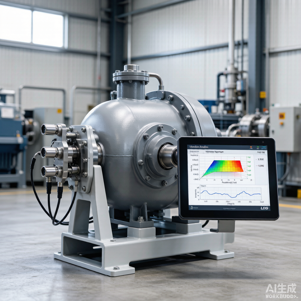
Figure 1: Vibration analysis equipment with accelerometer sensors on compressor bearing housing
4. Spectral Analysis Techniques
The vibration spectrum decomposes the overall vibration into its frequency components, revealing the specific sources of mechanical excitation. Each fault type produces a characteristic spectral pattern.
4.1 Common Spectral Patterns
| Frequency Component | Fault Indication | Confirmatory Evidence |
|---|---|---|
| 1x running speed | Unbalance or bend in shaft | Phase stable across bearings |
| 2x running speed | Mechanical or thermal misalignment | High axial vibration |
| 3x-6x running speed | Looseness or play in running gear | Harmonic series present |
| Sub-synchronous (<1x) | Oil whirl, rub, or bearing instability | Orbit analysis confirms |
| High frequency (5-20 kHz) | Bearing element impacts | Envelope spectrum analysis |
4.2 Reciprocating Compressor Specifics
Reciprocating compressors produce unique vibration signatures due to the intermittent nature of gas compression forces. Analysis requires crank-angle referenced measurement and time waveform examination in addition to spectral analysis.
- Use crank angle encoder for phase-referenced vibration analysis
- Examine time waveform for impact events at valve opening/closing
- Monitor crosshead knocking as indicator of clearance issues
- Track frame flexibility vibration for foundation integrity assessment
- Compare cylinder-to-cylinder vibration balance for uniformity check
5. Orbit Analysis and Shaft Centerline
Orbit analysis displays the dynamic path of the shaft center within the bearing clearance. Two proximity probes mounted 90 degrees apart provide X-Y displacement data that reveals bearing wear, oil whirl, rubs, and shaft misalignment.
- Circular orbit: normal condition with adequate oil film
- Elliptical orbit: misalignment or preload condition
- Inner loop orbit: oil whirl or sub-synchronous instability
- Flattened orbit: bearing wear with increased clearance
- Erratic orbit: rub condition or severe looseness
6. Envelope Analysis for Bearing Fault Detection
Envelope analysis (demodulation) is a powerful technique for early-stage bearing fault detection. By extracting the high-frequency impact energy modulated by bearing defect frequencies, envelope analysis can identify bearing degradation months before traditional vibration levels exceed alarm thresholds.
| Bearing Defect | Characteristic Frequency | Calculation Basis |
|---|---|---|
| Outer race defect | BPFO | N/2 x (1 – d/D cos a) x RPM |
| Inner race defect | BPFI | N/2 x (1 + d/D cos a) x RPM |
| Ball defect | BSF | D/2d x (1 – (d/D cos a)^2) x RPM |
| Cage defect | FTF | 1/2 x (1 – d/D cos a) x RPM |
7. Continuous Monitoring vs. Periodic Survey
The choice between continuous online monitoring and periodic walk-around surveys depends on equipment criticality, failure development speed, and available resources. Critical compressors warrant permanent online systems, while less critical units may be adequately monitored through periodic route-based surveys.
- Online systems: real-time alerts, continuous trending, automated diagnostics
- Route-based: lower cost, requires trained technician, periodic data gaps
- Hybrid approach: online for critical, route-based for auxiliary equipment
- Wireless sensors: emerging technology for cost-effective continuous monitoring
- Integrate vibration data with process data for comprehensive analysis
Source: Compressor Technology Editorial Reference